Understanding how to properly wire a proximity sensor is crucial for ensuring reliable operation in industrial automation, machinery safety systems, and various electronic applications. This guide provides a clear, step-by-step explanation of typical proximity sensor wiring configurations, using common real-world examples and diagrams. Proximity sensors, which detect the presence or absence of an object without physical contact, come in several types including inductive, capacitive, and ultrasonic. Each type may have specific wiring considerations, but many share similar basic connection principles.
A standard three-wire DC proximity sensor is one of the most common configurations found in practice. Typically, these three wires are color-coded: brown for positive power supply, blue for negative or common, and black for the output signal. The brown wire connects to the positive terminal of a DC power source, usually within a range of 10-30V DC. The blue wire connects to the negative terminal of the same power source and also often serves as the common reference point. The black wire is the switched output. In a normally open (NO) configuration, this black wire will supply voltage to the load (like a PLC input, relay, or indicator lamp) when a target is detected. The load is then connected between the black wire and the positive supply or back to the blue common, depending on the sensor's sinking (NPN) or sourcing (PNP) design. This distinction between NPN and PNP is fundamental. A PNP sensor switches the positive voltage to the load; its output wire goes high when activated. An NPN sensor switches the negative or ground side; its output wire goes low when activated. Misidentifying these can lead to incorrect circuit operation.
For a practical wiring example, consider connecting a PNP, normally open inductive proximity sensor to a programmable logic controller (PLC) digital input module. First, verify the sensor's operating voltage (e.g., 24V DC). Connect the brown wire to the +24V DC terminal of the power supply. Connect the blue wire to the 0V (common) terminal of the same supply. The black output wire is connected directly to the designated PLC input channel terminal. The PLC input module itself, configured for a sourcing input, will have its common terminal connected to the 0V supply. When a metal target enters the sensor's detection field, the sensor internally connects the black wire to the internal positive supply, sending a 24V signal to the PLC input, registering as a logic '1'. A two-wire AC proximity sensor simplifies wiring by having only two leads, which are connected in series with the load and the AC power source (e.g., 120V AC). Care must be taken to ensure the load's current draw falls within the sensor's minimum and maximum ratings to guarantee proper switching.
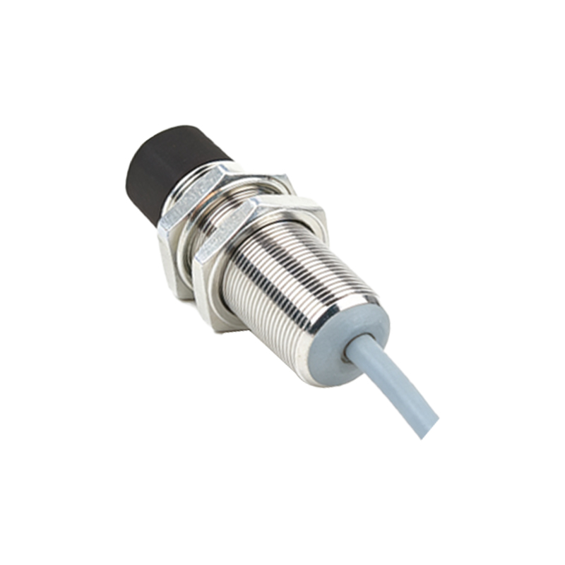
When examining a physical wiring diagram or connecting a real sensor, always prioritize safety. Disconnect all power before beginning any wiring work. Carefully consult the manufacturer's datasheet or the label on the sensor body for the specific wire color codes, voltage ratings, and output type, as standards can vary by region and manufacturer. Incorrect voltage application can instantly damage the sensor. Furthermore, consider the electrical environment. In applications with significant electromagnetic interference (EMI) from motors or drives, using shielded cable and grounding the shield at one end (typically the control panel end) can prevent false triggering. For sensors with built-in diagnostic LEDs, these provide visual confirmation of power and output status, aiding immensely in troubleshooting. Proper wiring is not just about making electrical connections; it involves integrating the sensor correctly into the control logic of the system. A correctly wired sensor forms the foundation for accurate object detection, precise counting, reliable position verification, and robust machine safety, ultimately contributing to efficient and trouble-free automated system performance.