Proximity switches, also known as proximity sensors, are indispensable components in modern industrial automation. They detect the presence or absence of an object without physical contact, offering reliability and longevity. Understanding how to correctly wire these sensors is crucial for ensuring system safety, functionality, and optimal performance. This guide provides a comprehensive overview of proximity switch wiring, covering common types, terminal identifications, standard wiring diagrams, and essential safety practices.
First, it's vital to identify the type of proximity switch you are using, as this dictates the wiring configuration. The two primary categories are based on the output circuitry:
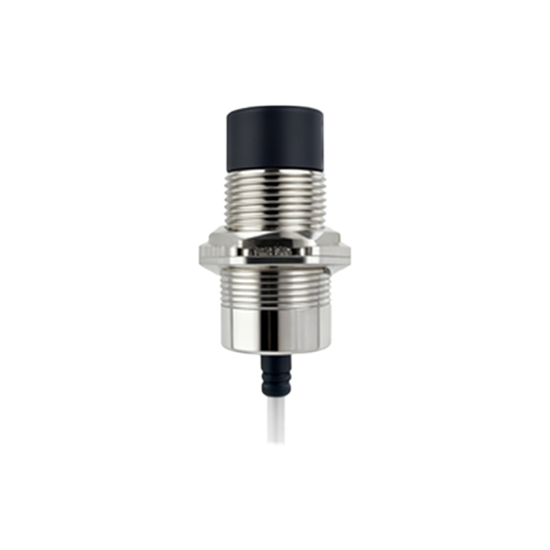
1. PNP (Sourcing) Switches: In a PNP switch, the output terminal acts as a positive source. When an object is detected, the switch connects the output terminal to the positive supply voltage, sourcing current to the load. The load (e.g., a PLC input, relay coil) is connected between the output terminal and the negative supply (0V).
2. NPN (Sinking) Switches: In an NPN switch, the output terminal acts as a negative sink. When activated, it connects the output terminal to the negative supply, sinking current from the load. Here, the load is connected between the positive supply and the output terminal.
Most industrial proximity switches have three wires or terminals, typically color-coded or labeled:
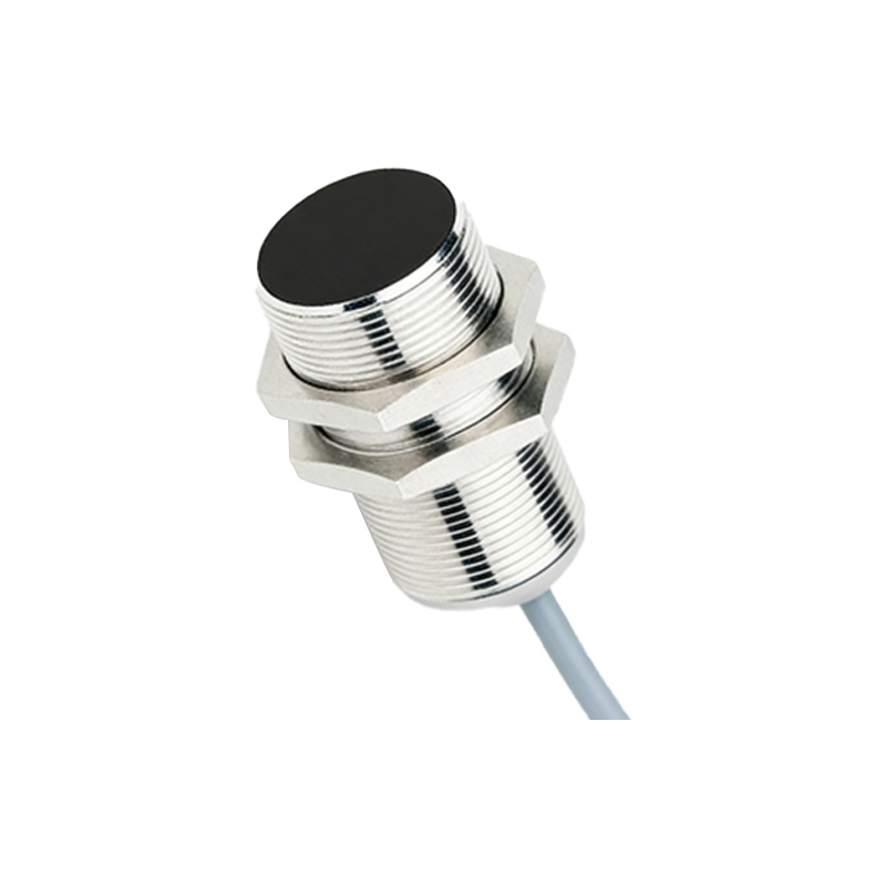
Brown (or +V / L+): This wire connects to the positive DC power supply voltage (e.g., 10-30V DC).
Blue (or 0V / L- / COM): This wire connects to the negative DC power supply voltage or common ground (0V).
Black (or OUT / Signal): This is the output signal wire. Its behavior (sourcing or sinking) depends on whether the sensor is PNP or NPN.
Some sensors may have a fourth wire (often white) for a complementary output or diagnostic function.
Standard 3-Wire DC Wiring Diagrams:
PNP (Sourcing) Normally Open (NO) Configuration:
Connect the Brown wire to the positive DC supply (+V).
Connect the Blue wire to the negative DC supply (0V).
Connect the Black output wire to one side of your load (e.g., PLC input module).
Connect the other side of the load to the negative supply (0V).
Operation: When no target is present, the output is OFF (no voltage on black wire). When a target is detected, the switch turns ON, sourcing positive voltage (+V) to the black wire, which then powers the load.
NPN (Sinking) Normally Open (NO) Configuration:
Connect the Brown wire to the positive DC supply (+V).
Connect the Blue wire to the negative DC supply (0V).
Connect the Black output wire to one side of your load.
Connect the other side of the load to the positive supply (+V).
Operation: When no target is present, the output is OFF (black wire is floating). When a target is detected, the switch turns ON, connecting the black wire to 0V, thus completing the circuit and allowing current to sink through the load.
Crucial Considerations for Correct Wiring:
1. Power Supply: Always use a stable, regulated DC power supply within the sensor's specified voltage range (commonly 10-30V DC). Incorrect voltage can damage the sensor.
2. Load Compatibility: Ensure your PLC input, relay, or other load is compatible with the sensor's output type (PNP vs. NPN) and current rating. Exceeding the maximum current can destroy the output transistor.
3. Shielded Cable: For long cable runs or in electrically noisy environments (near motors, VFDs), use shielded cable. Connect the shield to a proper earth ground at the power supply end only to minimize electromagnetic interference (EMI).
4. Polarity Protection: Double-check all connections before applying power. Reversing the brown and blue wires will likely damage the sensor permanently.
5. Wiring Distance: Adhere to manufacturer specifications for maximum cable length. Excessive length can cause voltage drop and signal degradation.
6. Safety First: Always isolate and lock out all power sources before beginning any wiring work. Verify wiring with a multimeter if possible.
Troubleshooting Common Issues:
Sensor Not Responding: Check power supply voltage and polarity. Verify the target is within the sensor's sensing range and is made of the correct material (ferrous for inductive