Hall effect switches are solid-state devices that utilize the Hall effect to detect the presence of a magnetic field and convert it into an electrical signal for switching operations. Unlike mechanical switches, they have no moving parts, offering high reliability, long operational life, and fast response times. The core principle hinges on the Hall effect, discovered by Edwin Hall in 1879. When a current-carrying conductor or semiconductor is placed perpendicular to a magnetic field, a voltage difference, known as the Hall voltage, is generated across the material. This voltage is perpendicular to both the current direction and the magnetic field.
A typical Hall effect switch integrates several key components on a single silicon chip: a Hall sensor element, a voltage regulator, a signal amplifier, a Schmitt trigger, and an output stage. The voltage regulator ensures stable operation despite fluctuations in the supply voltage. The thin Hall sensor plate, often made from a semiconductor material like gallium arsenide or indium antimonide, is the active region. When no magnetic field is present, the output from the Hall plate is minimal. However, when an external magnetic field of sufficient strength (exceeding a predefined threshold) is applied perpendicular to the chip's surface, the Lorentz force deflects the charge carriers (electrons or holes). This deflection creates a measurable Hall voltage across the plate.
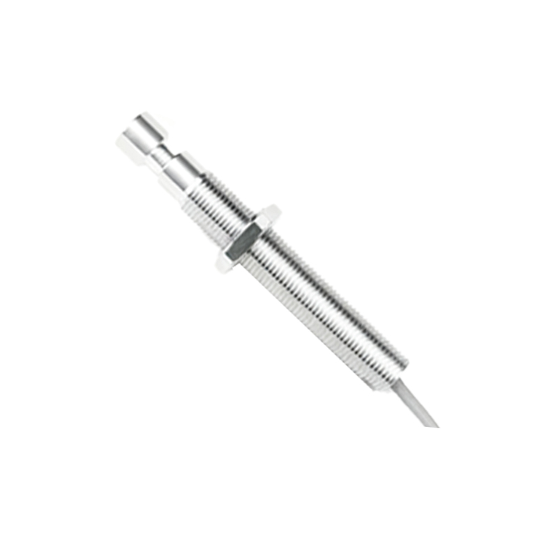
This tiny analog Hall voltage is first amplified by a high-gain amplifier. The amplified signal is then fed into a Schmitt trigger circuit. The Schmitt trigger is crucial as it provides hysteresis, meaning it has two distinct threshold levels: one for turning the output ON and a slightly lower one for turning it OFF. This hysteresis prevents rapid, unwanted switching (chatter) when the magnetic field strength is near the trigger point, such as from vibrations or minor field variations. Once the amplified signal exceeds the "ON" threshold, the Schmitt trigger swiftly changes the state of the output transistor.
The output stage is typically an open-collector NPN transistor or an open-drain MOSFET. In the absence of the required magnetic field, the output transistor is OFF (non-conducting), presenting a high-impedance state. When the magnetic flux density surpasses the operate point (B_OP), the transistor switches ON (saturates), effectively connecting the output pin to ground. The switch remains ON until the magnetic field decreases below the release point (B_RP), which is lower than B_OP due to the built-in hysteresis. At this point, the transistor turns OFF again. This digital ON/OFF behavior makes Hall switches ideal for direct interfacing with microcontrollers, logic circuits, or relays.
Two primary magnetic actuation methods are used: head-on (frontal) and slide-by (lateral) actuation. In head-on actuation, a magnet approaches the branded face of the switch directly. The output switches when the magnetic field component perpendicular to the chip reaches the threshold. In slide-by actuation, the magnet moves parallel to the switch surface, and the output toggles as the south and north poles pass by, often used in speed sensing or counting rotations.
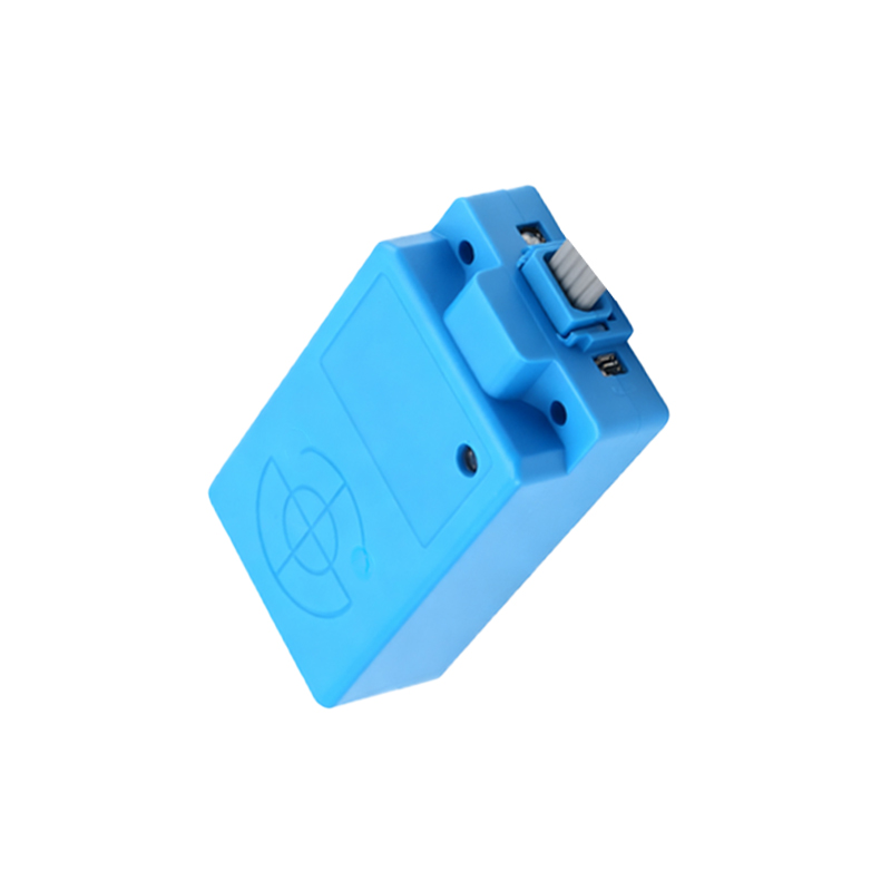
Key performance parameters include operate and release points (measured in Gauss or Tesla), hysteresis width, supply voltage range, output current capability, and response frequency. Their robustness against environmental contaminants like dust, moisture, and oil, coupled with silent operation, makes them indispensable in automotive systems (for gear position, seatbelt latches, brake pedals), industrial automation (position limit sensing, flow meters), consumer electronics (laptop lid closure, smartphone flip covers), and brushless DC motor commutation. Understanding this working principle enables engineers to effectively select and implement these versatile sensors for precise, contactless magnetic detection and switching tasks.