Proximity sensors are indispensable components in modern industrial automation, providing non-contact detection of metallic or other target objects. Their reliability is crucial for maintaining continuous production lines, robotic assembly systems, and safety interlocks. However, like all electronic devices, they are susceptible to failure. A systematic troubleshooting approach is essential for minimizing downtime. This guide outlines a professional, step-by-step fault diagnosis and rectification process.
Phase 1: Initial Symptom Analysis and Safety
Before any physical intervention, conduct a thorough operational analysis. Document the specific failure symptom: Is the sensor providing a constant ON signal, a constant OFF signal, an intermittent signal, or no output at all? Correlate this with the machine's behavior. Crucially, follow Lockout-Tagout (LOTO) procedures. De-energize and isolate the associated electrical circuit and mechanical system to ensure a safe working environment. Gather necessary documentation, including the sensor datasheet, wiring diagrams, and the machine's PLC logic overview.
Phase 2: Visual and Physical Inspection
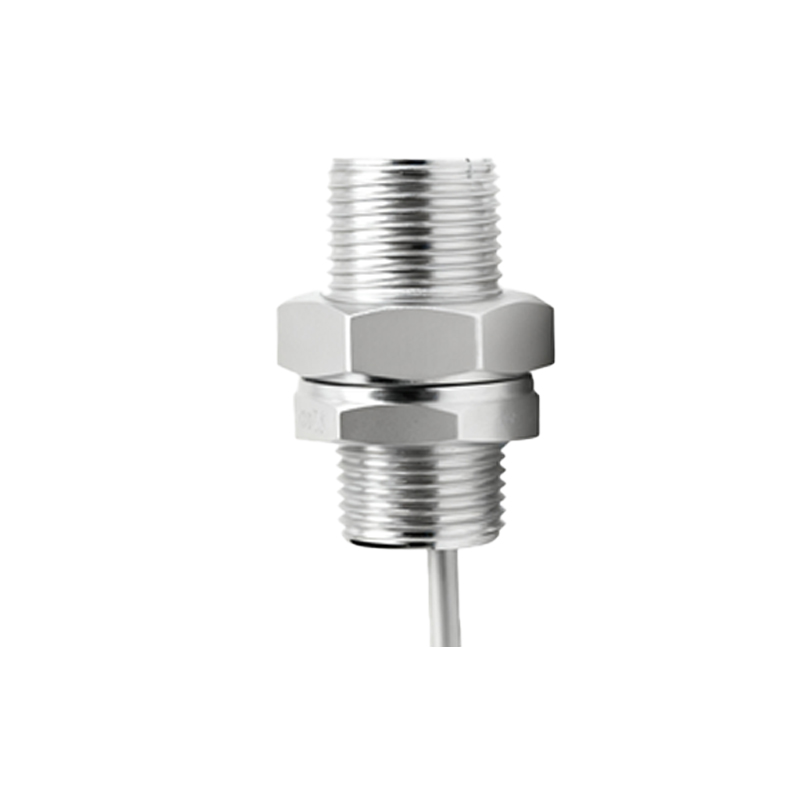
Begin with a detailed external examination.
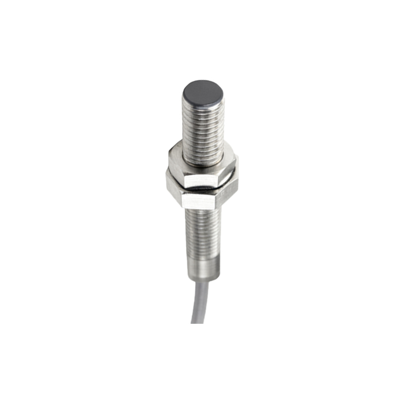
Sensor Body: Check for physical damage, cracks, or signs of impact. Verify the mounting integrity; loose mounting can alter the sensing distance.
Sensing Face: Inspect for accumulation of metal shavings, dirt, oil, or coolant. These contaminants can cause false triggering or shielding.
Target Object: Confirm the target's presence, material (must be within sensor specifications), size, and alignment. Ensure the target enters the sensor's nominal sensing range (Sn). A worn or misaligned target is a common failure point.
Environment: Assess ambient conditions for excessive heat, cold, moisture, or chemical exposure beyond the sensor's IP rating and temperature specifications.
Phase 3: Electrical and Signal Verification
Using appropriate multimeters and possibly an oscilloscope, proceed with electrical checks.
Power Supply: Measure the voltage at the sensor's terminals. Ensure it matches the rated supply voltage (e.g., 10-30 VDC). Voltage drops or ripple can cause erratic behavior.
Wiring and Connections: Inspect the cable for cuts, pinch points, or insulation damage. Check terminal blocks, connectors, and plugs for corrosion, looseness, or broken wires. A continuity test can identify open or short circuits.
Output Signal: For a DC sensor, measure the output voltage in ON and OFF states. A sinking (NPN) sensor should pull the signal line close to 0V when active. A sourcing (PNP) sensor should pull it close to the supply voltage. Compare readings with datasheet values. Use an oscilloscope to check for signal noise or instability.
Load Check: Verify the sensor's load (e.g., PLC input, relay coil) is within its maximum current rating. An overloaded output can fail.
Phase 4: Functional Testing and Parameter Adjustment
If electrical parameters are correct, perform controlled functional tests.
Bench Test: If possible, disconnect the sensor and test it in a known-good setup with a representative target. This isolates the sensor from machine-side issues.
Sensitivity/Response Adjustment: Some inductive and capacitive sensors feature a potentiometer for adjusting sensitivity. Refer to the manual. Slightly increase sensitivity if the sensor fails to detect, but avoid over-sensitivity which can cause false triggers from background objects.
Frequency Response: For high-speed applications, ensure the sensor's switching frequency is not exceeded by the target's passage speed.
Phase 5: Interference and System Integration Diagnosis
Persistent intermittent faults often point to external interference or system issues.
Electrical Noise: Identify potential noise sources like variable frequency drives (VFDs), welding equipment, or large motors. Ensure sensor cables are shielded, and the shield is properly grounded at one end only. Keep sensor cables separate from power lines.
Mutual Interference: Maintain adequate distance between multiple proximity sensors to prevent them from affecting each other. Consult datasheets for recommended separation distances.
PLC/Controller Logic: Review the PLC program. The issue might lie in the logic (e.g., timer settings, counter logic) rather than the sensor hardware itself. A forced input test within the PLC can confirm sensor signal reception.
Phase 6: Final Actions: Replacement and Documentation
If all previous steps confirm sensor failure, proceed with replacement.
Replacement: Use an identical model or a verified equivalent with matching specifications (type, sensing distance, output configuration, voltage, housing size, and connector). Ensure correct wiring according to the datasheet (brown/+V, blue/0V, black/output).
Post-Repair Verification: After installation, perform a full operational test across the entire