Wiring a proximity sensor correctly is fundamental to ensuring reliable operation in industrial automation systems. These non-contact sensors detect the presence or absence of an object and are crucial for tasks like counting, positioning, and machine safety. Incorrect wiring can lead to sensor failure, erratic machine behavior, or even damage to the control system. This guide provides a clear, professional procedure for wiring common types of proximity sensors, focusing on DC 3-wire configurations, which are the industry standard.
Before beginning any wiring work, adhere to critical safety protocols. Always disconnect and lock out all power sources to the control panel and the machine. Verify the power is off using a multimeter. Wear appropriate personal protective equipment (PPE). Carefully read the sensor's datasheet and the machine's electrical diagrams. Incorrect voltage application is a primary cause of sensor failure.
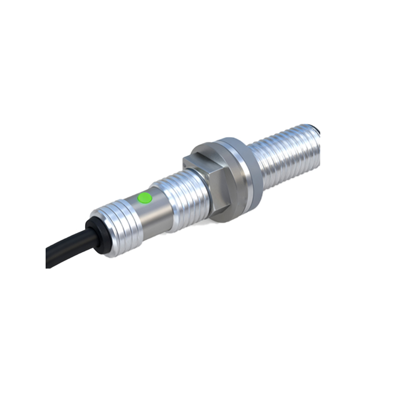
The first step is sensor identification. Proximity sensors are broadly categorized by their output type and wiring configuration. The most common types are:
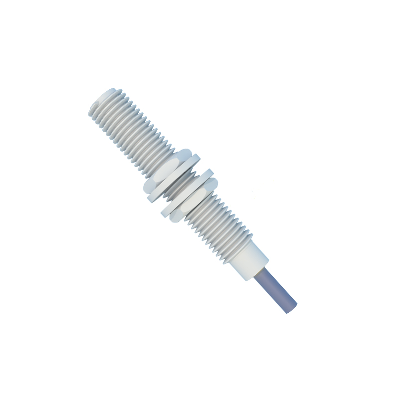
1. 2-Wire AC/DC Sensors: These act like a switch in series with the power line. They are simpler but have higher residual leakage current.
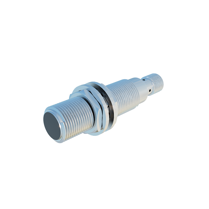
2. 3-Wire DC Sensors (NPN or PNP): This is the most prevalent configuration in modern PLC-based systems. They have separate power supply, output, and ground wires, offering better performance.
3. 4-Wire Sensors (Dual Output): These combine both an NPN and a PNP output in one housing.
For this guide, we focus on 3-wire DC sensors. The wiring color code is typically standardized as per international norms (IEC): Brown for positive supply (+V), Blue for common negative (0V), and Black for the output signal. However, always confirm this with the manufacturer's label or datasheet, as variations exist.
Understanding NPN vs. PNP Sourcing:
This is the most critical concept in DC sensor wiring. The terms refer to the type of transistor used in the sensor's output stage and determine how the output signal is switched.
PNP (Sourcing) Output: The output wire (Black) switches the positive voltage. When the sensor detects a target, it connects the output wire to the positive supply (+V). The load (e.g., a PLC input) must be connected between the output wire and the negative (0V). Think: PNP = Positive-switched, Positive-sourced.
NPN (Sinking) Output: The output wire (Black) switches the negative or ground path. When activated, it connects the output wire to the negative supply (0V). The load must be connected between the positive supply (+V) and the output wire. Think: NPN = Negative-switched, Negative-sourced.
Matching the sensor type (NPN or PNP) to your controller's input circuit is essential. Most PLCs and controllers can be configured for either sourcing or sinking input modes, but the sensor and input must be complementary.
Step-by-Step Wiring Procedure for a 3-Wire DC Proximity Sensor:
1. Power Supply: Ensure you have a stable DC power supply matching the sensor's voltage rating (e.g., 10-30 VDC). Connect the supply's positive (+) terminal to the sensor's Brown wire. Connect the supply's negative (-) terminal to the sensor's Blue wire.
2. Connecting the Load (e.g., PLC Input):
For a PNP Sensor: Connect the load (one side of your PLC digital input module) to the sensor's Black output wire. Connect the other side of the load to the power supply's negative (0V/Blue) terminal. When the sensor activates, +V (sourced) will flow through the Black wire, into the PLC input, and out to 0V, completing the circuit.
For an NPN Sensor: Connect one side of the load to the power supply's positive (+V/Brown) terminal. Connect the other side of the load to the sensor's Black output wire. When activated, the sensor connects the Black wire to 0V, allowing current to sink from the load, through the Black wire, to ground.
3. Shield Connection (if applicable): Many sensors have a shielded cable or a separate drain wire. This shield should be connected to a solid earth ground at the control panel end only to minimize electrical noise interference. Do not connect both ends.
4. Testing: After securing all connections, restore power. Use the sensor's indicator LED (if present) to verify detection. Use a multimeter to