Building a laser sensor is a fascinating project that combines principles of optics, electronics, and signal processing. Whether for industrial automation, security systems, or hobbyist experiments, a custom laser sensor offers flexibility and a deep understanding of detection technology. This guide provides a step-by-step approach to constructing a basic yet functional laser sensor system.
The core principle involves a laser emitter and a photodetector. The laser beam is directed towards the detector. When an object interrupts the beam, the change in light intensity at the detector is converted into an electrical signal, triggering an output. The system's complexity can be scaled based on required sensitivity, range, and environmental conditions.
First, select your core components. For the laser emitter, a low-power Class II or IIIA laser diode (e.g., 650nm, 5mW) is commonly used for safety and availability. Ensure it has a constant current driver module to maintain stable output and prevent damage. For the photodetector, a phototransistor or a photodiode is suitable. Phototransistors offer higher sensitivity but slower response, while photodiodes are faster. A Light-Dependent Resistor (LDR) is a simpler, cheaper alternative for slower applications. You will also need a lens or collimator for the laser to create a tight, focused beam, improving range and accuracy.
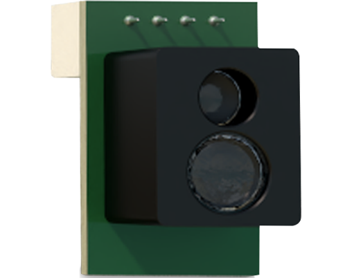
The electronic circuit is the system's brain. The detector component acts as a variable resistor. In a dark state (beam blocked), its resistance is high; when illuminated, resistance drops. This change can be measured using a voltage divider circuit. Connect the photodetector in series with a fixed resistor between the supply voltage (e.g., 5V) and ground. The junction point between them becomes your signal output. When light hits the detector, the voltage at this point changes significantly.
This analog signal is often too weak or noisy for direct use. Therefore, incorporating an operational amplifier (op-amp) in a comparator configuration is highly recommended. The comparator compares the signal voltage from the detector circuit against a preset reference voltage (adjustable via a potentiometer). When the beam is intact, the signal voltage is above the reference, and the comparator outputs a logic HIGH (e.g., 5V). When the beam is broken, the signal voltage falls below the reference, causing the comparator to switch to a logic LOW (0V). This provides a clean, digital on/off signal.

Power management is crucial. Use a stable DC power supply, such as a 9V battery with a 5V voltage regulator (like a 7805 IC) or a dedicated bench power supply. Decoupling capacitors (e.g., 100nF ceramic) near the power pins of active components (laser driver, op-amp) are essential to filter noise.
Assembly begins with mechanical mounting. Securely fix the laser emitter and photodetector on a stable platform, ensuring precise alignment. For long-range applications, use mounting brackets with fine adjustment screws. Alignment is critical: power the laser and adjust the detector's position until it receives maximum illumination. The comparator's reference potentiometer should then be adjusted so the output switches state reliably when a thin object breaks the beam.
For enhanced functionality, consider adding a microcontroller (e.g., Arduino, PIC). This allows for advanced features like adjustable sensitivity via software, timing functions to measure interruption duration, communication protocols (UART, I2C) for system integration, and immunity to ambient light changes through pulsed laser operation and synchronized detection.
Environmental factors greatly affect performance. Ambient light is the primary干扰. Using a modulated (pulsed) laser signal and a tuned receiver circuit that only responds to that specific frequency can eliminate most ambient light interference. For the laser itself, a visible red laser is easier to align, but an infrared (IR) laser diode paired with an IR-filtered photodetector offers discretion and reduced distraction. Always prioritize safety. Never look directly into the laser beam or its reflections. Use appropriate laser safety goggles matching the laser's wavelength during alignment and testing.
Testing and calibration validate your build. Use an oscilloscope to observe the signal at the photodetector output and the comparator output. Verify the switching is sharp and consistent. Test the sensor's range and minimum detectable object size. Document the reference voltage setting for your standard operating conditions.
In conclusion, building a laser sensor is a highly educational hands-on project. By carefully selecting components, designing a robust comparator circuit, and meticulously aligning the optics, you can create a reliable sensor tailored to specific needs. This foundational knowledge serves as a springboard for more advanced projects like laser triangulation sensors, LiDAR modules, or intricate safety curtains. Remember, continuous iteration and testing are key to engineering a resilient and effective system.