In the realm of industrial automation and control systems, proximity sensors are indispensable components for non-contact detection of metallic or non-metallic objects. Their reliability is paramount for ensuring seamless operation of machinery, safety interlocks, and process control. However, a surprisingly common and potentially critical installation error is the reversal of sensor wiring. This article, from an electrical engineering perspective, delves into the technical consequences, diagnostic procedures, and corrective measures for incorrectly wired proximity sensors, focusing primarily on common 3-wire DC types (PNP and NNP sourcing configurations).
Fundamentally, a 3-wire DC proximity sensor comprises three leads: supply voltage positive (V+ or brown wire typically), supply voltage negative (0V or blue wire), and the signal output line (black wire). The sensor's internal circuitry is designed for a specific polarity. Reversing the supply wires—connecting brown to 0V and blue to V+—constitutes a direct polarity reversal. Modern sensors often incorporate reverse polarity protection diodes. When activated, these diodes prevent current flow, rendering the sensor completely inert. No LED indicators will illuminate, and no output signal will be generated. While this protects the sensor's internal electronics from immediate catastrophic failure, it creates a "no device detected" fault condition in the control system, halting the intended process.
A more insidious and damaging scenario involves miswiring the output signal line with the supply lines. For instance, connecting the sensor's black output wire directly to the positive supply rail while the brown wire is connected to the PLC input can have severe repercussions. In a PNP (sourcing) sensor, the output transistor is effectively short-circuited. This can cause the output switching transistor to fail, often in a shorted state. The immediate symptom may be a sensor that appears "always on," regardless of target presence, potentially sending a constant 24V signal to the PLC input. This not only destroys the sensor but can also risk damaging the PLC's input channel due to sustained overvoltage or incorrect current sourcing.
Diagnosing a wiring reversal begins with a systematic approach. First, always consult the sensor's datasheet and the machine's electrical schematic—these are the primary references. Visually inspect the wiring against the terminal designations (e.g., 1-Brown/V+, 2-Black/Output, 3-Blue/0V). Use a multimeter to verify voltage at the sensor connector: between the supposed V+ and 0V terminals, you should measure the nominal DC supply voltage (e.g., 24VDC). If the voltage is zero or negligible, the supply polarity at the source may be incorrect. Next, observe the sensor's status LED (if present) when power is applied. No illumination strongly suggests reverse polarity or no power. An LED that is constantly lit, even without a target, may indicate internal damage from previous miswiring.
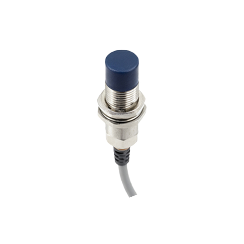
Corrective action is straightforward once the error is identified. Always isolate and lock out power before making any changes. Re-wire the connections precisely according to the manufacturer's pinout. For a standard 3-wire DC sensor: Brown wire to DC+, Blue wire to DC-, and Black wire to the PLC input or load. After securing connections, restore power and test functionality by presenting a target to the sensor. Verify the output state change with a multimeter or the PLC's input status indicator.
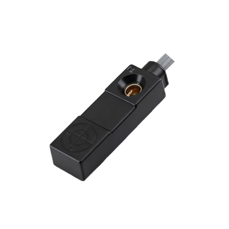
To prevent such errors, adopt disciplined installation practices. Use color-coded cables consistently throughout the facility. Implement a pre-power-up checkout procedure where a second technician verifies wiring. Clearly label all sensor cables and terminals. For critical applications, consider using sensors with M12 connectors with coded pins, which physically prevent incorrect mating. Furthermore, investing in sensors with robust diagnostic LEDs (power, output status) aids immensely in quick troubleshooting.
In conclusion, while proximity sensors are robust devices, reversing their wiring bypasses their designed operational parameters. The outcomes range from simple non-operation due to protective features to permanent hardware damage causing erratic machine behavior. A methodical approach to installation, verification, and diagnosis, rooted in a solid understanding of sensor specifications and electrical fundamentals, is the most effective strategy to eliminate downtime, prevent component damage, and ensure system integrity. Remember, in control systems, correctness at the point of connection is the first and most crucial line of defense.