In the world of industrial automation and machinery monitoring, the accurate measurement of rotational speed is a fundamental requirement for ensuring efficiency, safety, and predictive maintenance. Among the various technologies employed for this task, proximity switch speed sensors stand out for their reliability, non-contact operation, and versatility. This article delves into the core principles of these sensors, explores their diverse applications, and provides a practical guide for selection and implementation.
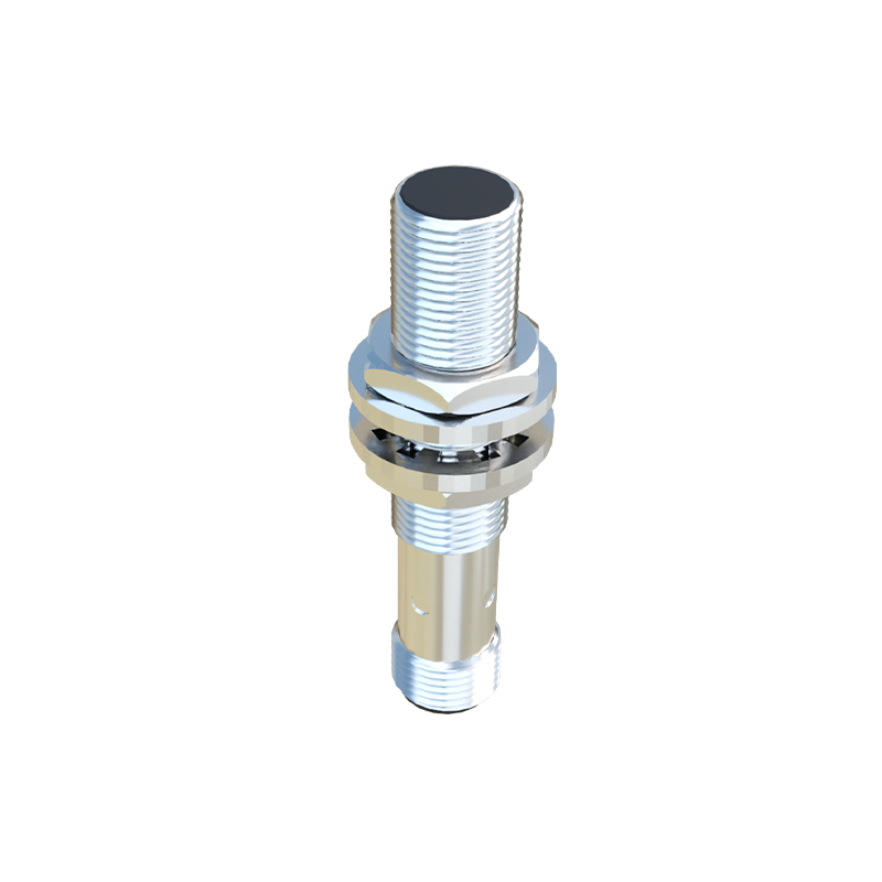
At its heart, a proximity switch speed sensor is a non-contact electronic device designed to detect the presence or passage of a metallic target and convert this detection into a measurable speed signal. Unlike mechanical tachometers, they do not require physical contact with the rotating component, thereby eliminating wear and tear and allowing for measurement in harsh or inaccessible environments. The most common operating principle is the inductive proximity sensor. It contains an oscillator circuit that generates a high-frequency electromagnetic field at its active face. When a ferrous or non-ferrous metallic target (such as a gear tooth, keyway, or bolt head) enters this field, eddy currents are induced in the target. This causes a change in the oscillation amplitude, which is detected by a threshold circuit, triggering a solid-state switch output—typically a digital pulse. By counting these pulses over a known time interval, the rotational speed (RPM) or linear speed can be precisely calculated. Other types include capacitive sensors for non-metallic targets and magnetic sensors (Hall-effect or magnetoresistive) that detect the movement of a permanent magnet.
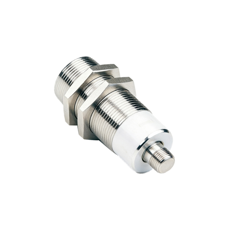
The applications for proximity switch speed sensors are vast and span numerous industries. In automotive manufacturing and testing, they monitor engine RPM, wheel speed, and camshaft/crankshaft position. Within conveyor systems, they track belt speed to synchronize processes or detect slippage. On wind turbines, they are crucial for monitoring the main shaft speed to prevent overspeed conditions. They are integral to pump and motor control systems, providing feedback for variable frequency drives (VFDs). In metalworking, they measure the speed of rolling mills, lathes, and cutting tools. A key safety application is in machinery guarding, where they can be used as part of a safety interlock system to confirm a shaft has stopped rotating before allowing access for maintenance.
Selecting the right proximity sensor for speed measurement involves several critical parameters. First, the sensing distance: this must be sufficient to reliably detect the target without physical contact, considering installation tolerances and target movement. Second, the target material and size: inductive sensors require metal, and the target must be large enough to cause a detectable change in the field. Third, the output type: PNP (sourcing) or NPN (sinking) digital outputs are standard, but some sensors offer analog (4-20 mA or 0-10V) outputs proportional to speed. Fourth, the switching frequency: this must be high enough to handle the maximum pulse frequency generated by the target at top speed. For instance, measuring a 60-tooth gear at 10,000 RPM requires a sensor capable of handling 10,000 pulses per second. Fifth, environmental factors: the sensor's housing material (often stainless steel or nickel-plated brass) and ingress protection (IP) rating must withstand exposure to coolants, oils, dust, and temperature extremes. Finally, the physical form factor, such as tubular (threaded barrel) or rectangular, must suit the mounting location.
Installation and setup are straightforward but vital for optimal performance. The sensor should be mounted securely to minimize vibration. The alignment and gap between the sensor face and the target are critical; following the manufacturer's specified nominal sensing distance (Sn) is essential. The target should be clean and of consistent geometry. For gear measurement, the sensor is typically aligned with the tooth flank. The output is then connected to a frequency counter, tachometer, or a programmable logic controller (PLC) input module programmed to calculate RPM.
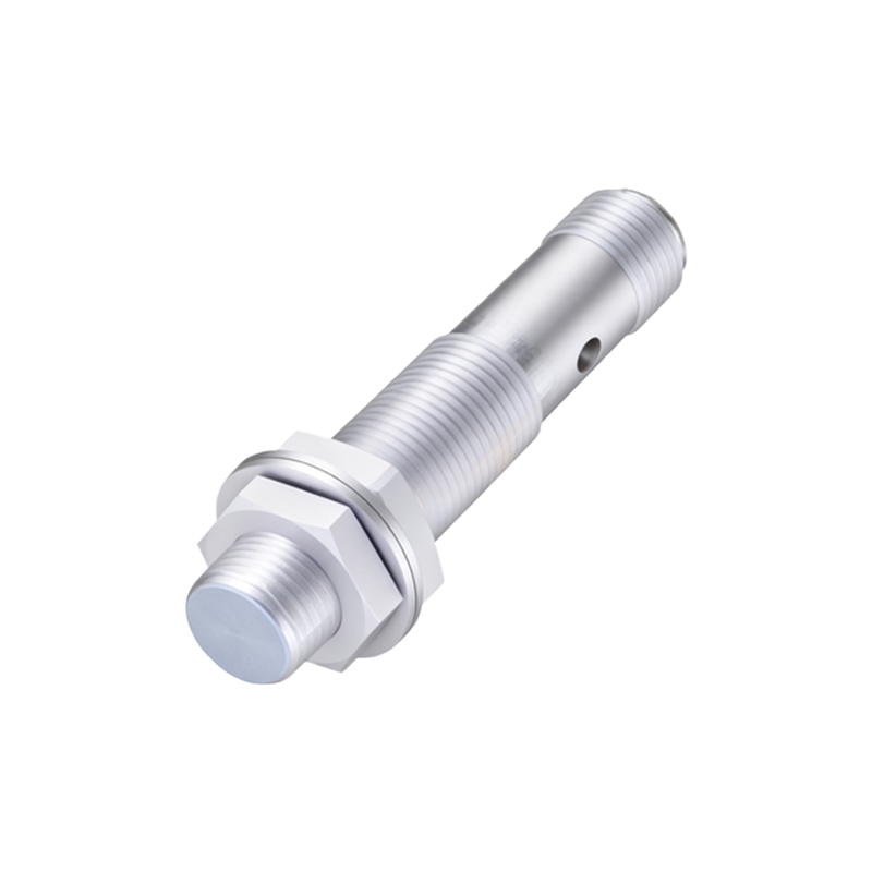
In summary, proximity switch speed sensors are indispensable components in modern industrial systems. Their non-contact nature ensures longevity and minimal maintenance, while their robust design allows operation in challenging conditions. By understanding their operating principles, carefully matching the sensor specifications to the application requirements, and following proper installation practices, engineers and technicians can achieve highly reliable and accurate speed monitoring. This contributes directly to improved process control, enhanced machine safety, and the valuable data needed for condition-based maintenance strategies, ultimately driving operational efficiency and reducing downtime.