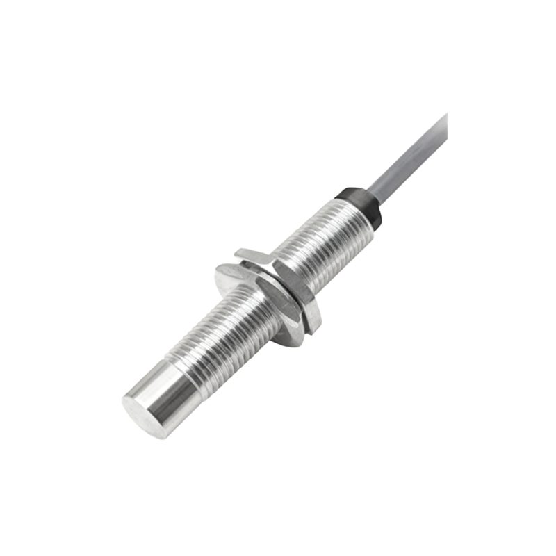
In the realm of industrial automation and control systems, proximity sensors stand as fundamental components for non-contact object detection. A critical aspect of their installation and functionality is understanding the "front face" or sensing face of the device. This article delves into the anatomy, function, and practical considerations of the proximity sensor's front face, providing essential knowledge for engineers and technicians.
The front face of a proximity sensor is precisely the surface from which the sensor emits its detection field and receives the return signal or disturbance. It is the active interface between the sensor and its target. This face is typically, though not always, a flat, smooth surface made of a material that is transparent to the sensor's operating principle. For inductive proximity sensors, which detect metallic objects, the front face is often a rugged, wear-resistant plastic (like PBT or PPS) that covers the internal coil and ferrite core. This material allows the oscillating electromagnetic field to pass through unimpeded. For capacitive sensors, the front face itself usually acts as one electrode of the capacitor, and it can detect both metallic and non-metallic materials based on changes in capacitance. Ultrasonic sensors have a transducer membrane on the front face that emits and receives sound waves, while photoelectric sensors feature a lens for focusing the light beam.
The design and markings on the front face are not arbitrary. They convey vital information. Most prominently, you will often find the manufacturer's logo, part number, and electrical specifications (voltage, current, output type). Crucially, many sensors feature LED indicators embedded near the front face. These LEDs provide immediate visual feedback on the sensor's status: power-on, output activation, and sometimes diagnostic modes (like short-circuit or overload warnings). The position of this LED is strategic, allowing for easy visibility during commissioning and troubleshooting without needing to view the sensor's body directly.
A key specification directly related to the front face is the "sensing distance," often denoted as Sn. This is the nominal distance at which a standard target will reliably trigger the sensor. It is measured perpendicularly from the front face. It is paramount to understand that this rated distance is achieved under ideal conditions with a specified standard target (e.g., a square of mild steel for inductive sensors). Factors like target material, size, shape, and environmental conditions can reduce the effective sensing range. Therefore, a common best practice is to install the sensor at 50-80% of its rated sensing distance to ensure reliable operation and account for mechanical tolerances or buildup of contaminants on the front face.
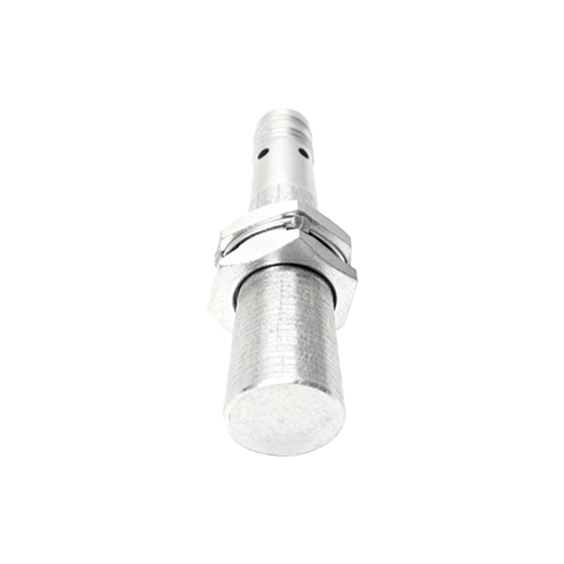
The orientation and mounting of the front face are critical for optimal performance. Sensors are designed to be mounted flush or non-flush. Flush-mountable sensors (also called shielded or embeddable) have their sensing field focused directly ahead from the front face. Their metal housing is designed to allow them to be installed flush with a metal bracket without the bracket itself triggering the sensor. Non-flush sensors (unshielded) have a more extended lateral sensing field. If their metal housing is mounted flush with metal, it can cause false triggering. Therefore, they require a non-ferrous surround or must be proud of the mounting surface. The installation drawings always specify the required clearance around the front face.
Protection of the front face is a major consideration in harsh industrial environments. Contaminants like dust, oil, coolant, metal chips, or paint overspray can accumulate on the front face. For inductive and capacitive sensors, a thin layer of non-conductive material might not affect performance significantly, but a thick buildup can attenuate the sensing field. For optical and ultrasonic sensors, any obstruction on the front face lens or transducer can severely degrade or completely block the signal. Selecting a sensor with an appropriate Ingress Protection (IP) rating (e.g., IP67, IP69K) is essential. Some applications employ sensors with a "flush" design to prevent material buildup or use accessories like protective caps or air blow-off devices to keep the front face clean.
In summary, the front face of a proximity sensor is its operational window to the world. Its construction defines the sensing technology, its markings provide critical data, and its condition dictates performance reliability. Proper selection, installation with correct clearances, and diligent protection of this front face are foundational practices for ensuring robust and fail-safe operation in any automated system. Ignoring these aspects can lead to erratic machine behavior, unnecessary downtime, and increased maintenance costs. Always refer to the manufacturer's datasheet for specific details regarding the front face characteristics, sensing profiles, and mounting requirements of your chosen sensor model.