In the world of automation and smart devices, proximity sensors play a crucial, often invisible role. A proximity sensor diagram is more than just a technical drawing; it is a visual key to understanding how these devices detect the presence or absence of nearby objects without any physical contact. This article delves into the core components illustrated in such diagrams, explains the working principles they represent, and explores the common types and their real-world applications.
At its heart, a standard proximity sensor diagram will typically break down the device into several key sections. The core is the sensing element or oscillator. In inductive and capacitive sensors, this is often a coil or a capacitor plate that generates an electromagnetic or electrostatic field. The diagram shows this field radiating from the sensor face. When a target object enters this detection field, it causes a measurable change—a dampening of oscillations in an inductive sensor or a change in capacitance in a capacitive sensor. This change is the primary signal.
The diagram then traces this signal to the signal conditioning circuit. This block is critical, as it amplifies the weak analog change from the oscillator and converts it into a clean, usable electrical signal. Following this, the processed signal is fed into an output switching circuit. This is where the sensor interfaces with the larger control system. The diagram will clearly indicate the output type, whether it's a transistor (NPN or PNP sourcing/sinking), a relay contact, or an analog voltage/current output. Wires for power supply (typically labeled Vcc/+, 0V/GND/-) and the output load connection are clearly marked, making the wiring process straightforward for engineers and technicians.
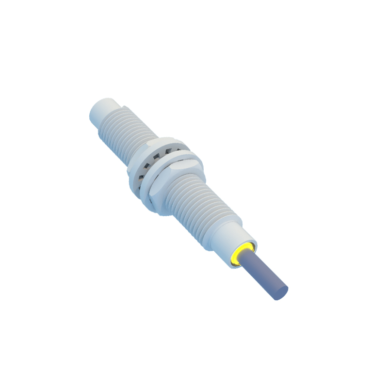
Understanding a diagram also requires knowing the sensor type it represents. The most common categories are:
1. Inductive Proximity Sensors: Their diagrams emphasize a coil oscillator. They detect only metallic objects (ferrous and non-ferrous) by disturbing the high-frequency electromagnetic field. The diagram often includes a note on the sensing distance and how it varies with different metals.
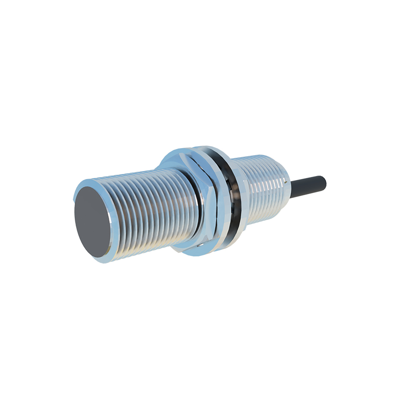
2. Capacitive Proximity Sensors: These diagrams show capacitor plates and can detect both metallic and non-metallic materials (plastics, liquids, wood) by measuring changes in the dielectric constant. They are ideal for level detection or seeing through non-metallic containers.
3. Photoelectric Sensors: While sometimes considered separately, their diagrams for diffuse-reflective types function as proximity sensors. The diagram shows an integrated emitter (LED) and receiver. It visualizes the light beam being projected and reflected back from the target object to the receiver, triggering the output.
4. Ultrasonic Proximity Sensors: These diagrams depict a transducer for emitting high-frequency sound waves and another for receiving the echo. The time-of-flight calculation for the sound pulse is the key principle illustrated.
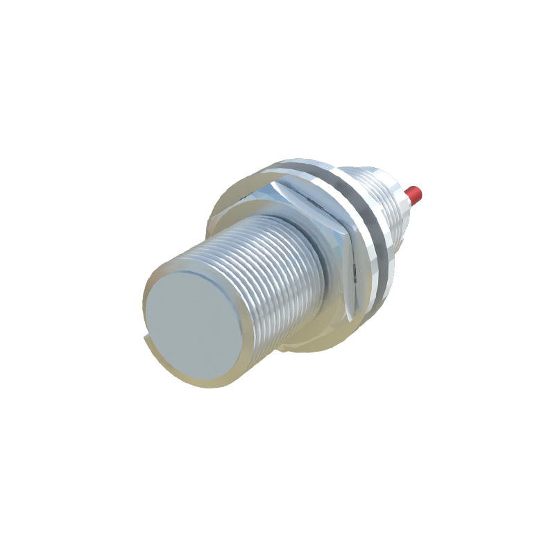
The practical value of studying these diagrams is immense. In industrial settings, a technician can use the wiring diagram to correctly integrate a sensor into a Programmable Logic Controller (PLC) system, ensuring proper sourcing or sinking configurations to avoid damage. For designers, the diagram reveals the sensor's blind zones, repeatability, and hysteresis—factors critical for precision applications like robotic positioning or assembly line counting.
Applications are vast. From the inductive sensor in a car that detects gear position or activates a parking assist warning, to the capacitive sensor in a touchscreen faucet or a smartphone that turns off the display when held to your ear, the underlying principle is mapped out in its diagram. In manufacturing, they are indispensable for object detection, counting, jam detection, and limit switching.
In conclusion, a proximity sensor diagram is a fundamental blueprint. It translates the abstract concept of contactless detection into a clear, component-by-component visual guide. By learning to read these diagrams, one gains insight into sensor selection, correct installation, and troubleshooting, unlocking the full potential of these versatile devices in an increasingly automated world. Whether you are a student, a hobbyist, or a seasoned engineer, this knowledge forms the foundation for working effectively with modern sensing technology.