Proximity sensors are fundamental components in modern industrial automation, offering non-contact detection of metallic and non-metallic objects. This practical training guide is designed for electrical engineers and technicians seeking to enhance their hands-on skills with inductive, capacitive, and magnetic proximity sensors. The focus is on real-world application, troubleshooting, and integration within control systems.
The training begins with sensor selection. Inductive sensors are ideal for detecting ferrous metals, with sensing ranges typically up to 15mm. Capacitive sensors can detect materials like plastics, liquids, or wood, making them versatile for level detection or material handling. Magnetic sensors, often used with cylinders, provide long-range detection in harsh environments. Understanding the specifications—such as nominal sensing distance (Sn), operating voltage (10-30V DC common), output type (PNP/NPN, NO/NC), and housing material (nickel-plated brass, stainless steel, or PBT plastic)—is critical for correct application.
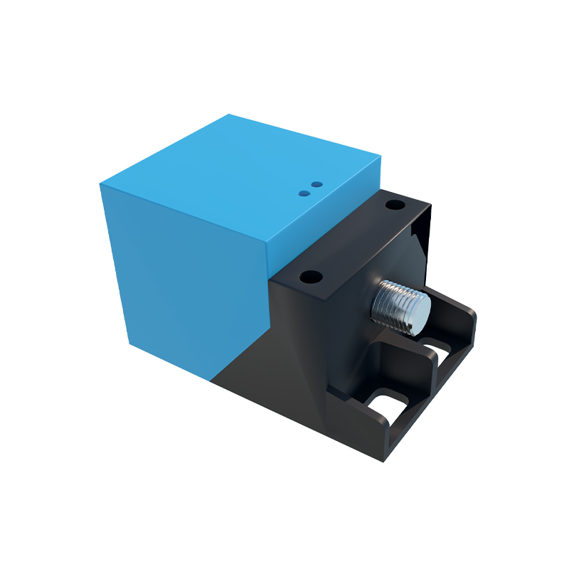
Wiring and installation form the core of the practical session. For a standard 3-wire DC sensor, connect the brown wire to +24V, the blue wire to 0V, and the black wire as the switching output to a PLC input module. Always refer to the datasheet, as wire colors can vary by manufacturer. A common mistake is mismatching PNP (sourcing) and NPN (sinking) outputs with the PLC's input type, which will prevent signal detection. Mounting is equally important; ensure the sensor is positioned perpendicular to the target, maintaining the recommended gap to avoid false triggers from lateral movement or vibration. Shielding (flush-mounted) sensors can be embedded in metal, while non-shielded types require a clear lateral area for proper operation.
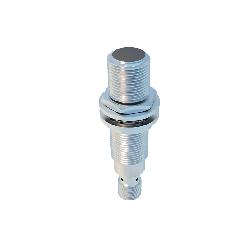
Configuration and testing involve adjusting sensitivity potentiometers on capacitive sensors or teaching-in procedures for analog-output models. Use a multimeter to verify output voltage in the active state. A key troubleshooting step is to check the sensor's LED indicator. A solid LED with no target present may indicate a wiring error, a damaged sensor, or excessive sensitivity causing interference from background objects. For inductive sensors, ensure the target material and size meet the minimum requirements; a small aluminum target may not be detected by a standard inductive unit, requiring a factor-of-reduction correction.
Integration with PLCs demonstrates the sensor's role in a control loop. Write a simple ladder logic routine where a sensor input triggers a timer or counter. Analog sensors (4-20mA or 0-10V) provide continuous data, such as distance or fill level, which can be scaled in the PLC for precise monitoring. Emphasize electrical noise immunity by using shielded cables, proper grounding, and separating signal lines from power cables in cable ducts. In high-speed counting applications, verify the sensor's switching frequency against the target's speed to avoid missed counts.
Advanced exercises include setting up a fail-safe monitoring system using two sensors in a redundant configuration or interfacing with safety relays for machine guarding. Simulate fault conditions like sensor misalignment, target surface contamination (oil, dust), and temperature extremes to observe performance degradation. Document all findings, including response time measurements and the effects of different target materials on sensing distance.
This hands-on approach builds competency in deploying proximity sensors reliably, reducing machine downtime, and optimizing automated processes. Regular practice with various models and scenarios is essential for mastering their application in complex industrial environments.