In industrial automation and process control, accurately measuring the frequency of rotating or reciprocating machinery is crucial for monitoring performance, preventing failures, and optimizing operations. While dedicated tachometers and encoders are common solutions, proximity switch sensors offer a robust, cost-effective, and versatile alternative for frequency measurement. This guide delves into the principles, methodologies, and best practices for using inductive, capacitive, and magnetic proximity sensors to determine rotational or vibrational frequency.
The fundamental principle is straightforward: a proximity sensor detects the presence or absence of a target object. By arranging for a target (like a gear tooth, keyway, bolt head, or a dedicated flag) to pass by the sensor face at regular intervals, the sensor generates a series of discrete output pulses. The frequency of this pulse train directly corresponds to the rotational or linear speed of the target. For a rotating shaft with a single target, one pulse is generated per revolution. Therefore, the frequency (f) in Hertz (Hz) equals the rotational speed (N) in Revolutions Per Second (RPS). To convert from the more common Revolutions Per Minute (RPM), the relationship is f(Hz) = N(RPM) / 60.
The choice of sensor type is paramount. Inductive proximity sensors are the most prevalent for metallic targets. They generate an electromagnetic field and detect eddy current losses in a conductive target. For frequency measurement, they excel in detecting ferrous and non-ferrous metals on rotating equipment. Capacitive proximity sensors can detect both metallic and non-metallic materials (plastic, wood, liquid) and are useful in applications where the target is non-conductive. Magnetic proximity sensors (or reed switches used with magnets) are ideal for harsh environments with dirt, dust, or moisture, as they rely on the presence of a magnetic field rather than physical proximity to a conductive surface.
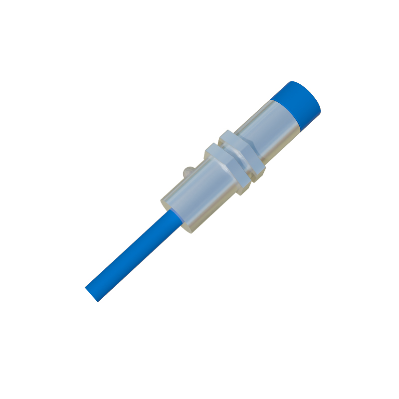
The system setup involves several critical steps. First, select a sensor with a sufficient switching frequency. The sensor's specified switching frequency must be significantly higher than the maximum frequency you intend to measure to ensure accurate pulse reproduction. A sensor with a 1 kHz switching frequency cannot reliably measure a 900 Hz signal. Second, ensure proper mounting and alignment. The sensor must be positioned within its specified sensing range, typically 0.5 to 15 mm for inductive types, to ensure consistent and reliable triggering without physical contact. Vibration or misalignment can cause erratic pulses. Third, the target design is crucial. The target size should be equal to or larger than the sensor's face for reliable detection. For high-resolution frequency measurement, multiple targets (like a gear with many teeth) can be used. If a gear with 'n' teeth is used, the output frequency is f = (N(RPM) n) / 60. This multiplies the frequency for a given RPM, allowing for more precise measurement at lower speeds or better resolution.
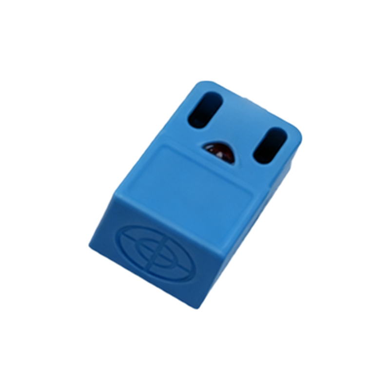
Signal conditioning and measurement form the next phase. The raw output from a proximity sensor is typically a digital signal (PNP/NPN). This signal can be fed directly into a frequency counter, a programmable logic controller (PLC) high-speed counter input, a frequency-to-voltage converter, or a data acquisition (DAQ) system. In a PLC, standard logic can be used to calculate frequency by measuring the time between consecutive pulses (period) and taking its reciprocal (f=1/T). For higher accuracy over short periods, the count of pulses over a fixed, precise time interval (like one second) provides the frequency directly. It is vital to account for noise and signal integrity. Using shielded cables, proper grounding, and keeping sensor wires away from power lines minimizes electromagnetic interference (EMI) that can create false pulses.
Practical applications abound. Common examples include monitoring motor RPM, conveyor belt speed, pump shaft rotation, fan speed, and the reciprocating frequency of presses or actuators. In vibration analysis, a proximity sensor fixed near a rotating shaft can help identify imbalance or misalignment by detecting variations in the fundamental rotational frequency. Troubleshooting common issues involves checking for inconsistent pulse generation (often due to target damage, contamination on the sensor face, or insufficient target material), signal dropouts (from wiring faults or excessive sensor-to-target gap), and measurement errors (from incorrect scaling in the PLC or DAQ software, or aliasing if the sampling rate is too low).
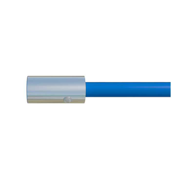
In conclusion, proximity switches are a highly effective tool for non-contact frequency measurement in industrial settings. Success hinges on selecting the right sensor type with an adequate switching frequency, ensuring meticulous mechanical installation and target design, and implementing robust signal processing. By mastering these elements, engineers can implement reliable and cost-efficient frequency monitoring systems that enhance predictive maintenance, quality control, and overall operational efficiency.