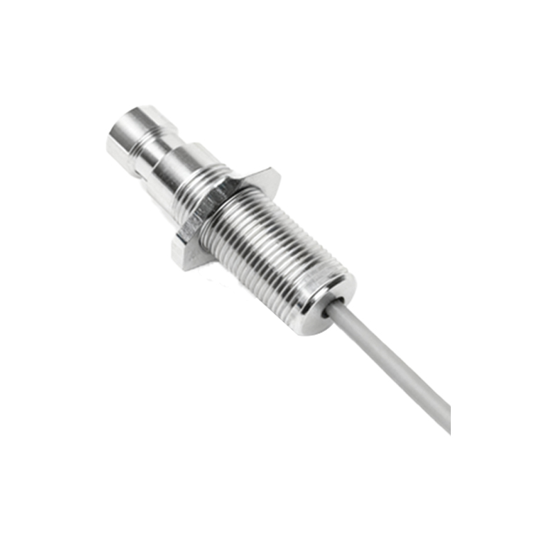
Proximity sensors are essential components in industrial automation, offering non-contact detection of metallic or non-metallic objects. Proper wiring is critical to ensure reliable operation, and understanding terminal configurations through wiring diagrams is key for engineers and technicians. This article provides a comprehensive guide to proximity sensor terminal wiring, supported by detailed diagrams and best practices for installation.
Proximity sensors typically feature three or four terminals, depending on the type (e.g., NPN, PNP, or AC/DC models). Common terminals include power supply (V+ and V-), output signal (OUT), and ground (GND). Wiring diagrams visually represent these connections, helping users avoid errors that could lead to sensor failure or system downtime. For instance, in a 3-wire DC sensor, the brown wire connects to positive voltage, blue to negative, and black to the output load. Incorrect wiring, such as reversing polarity, can damage the sensor or cause erratic behavior.
When interpreting proximity sensor terminal pictures, note the labeling on the sensor housing or datasheet. Labels like "L+" and "L-" indicate load connections, while "NO" (normally open) or "NC" (normally closed) denote output states. Diagrams often include symbols for power sources, loads (e.g., relays or PLCs), and protective devices like fuses. For AC sensors, terminals may include "L1" and "L2" for live and neutral lines. Always refer to manufacturer-specific diagrams, as standards can vary by brand (e.g., Omron, Siemens, or Schneider Electric).
Installation tips start with power disconnection to prevent electrical hazards. Use appropriate tools, such as wire strippers and crimpers, to secure connections to terminal blocks. Ensure wires are of correct gauge and insulation rating for the sensor's voltage and current specifications. For harsh environments, consider shielded cables to reduce electromagnetic interference. Mount the sensor securely, aligning it within its sensing range, and avoid placing metal objects nearby that could trigger false signals. After wiring, test the sensor with a target object to verify output response using a multimeter or PLC monitor.
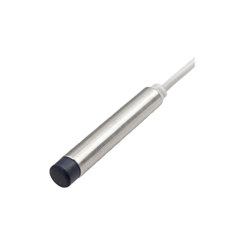
Common issues in wiring include loose terminals, which cause intermittent operation, and incorrect sourcing/sinking configurations. For example, NPN sensors sink current to ground, suitable for PLCs with positive logic, while PNP sensors source current from positive supply. Mixing these with incompatible controllers leads to malfunctions. Diagrams clarify this by showing current flow paths. Additionally, for sensors with diagnostic LEDs, wiring errors may be indicated by blinking patterns—consult manuals for troubleshooting.
In summary, proximity sensor terminal wiring diagrams are invaluable tools for safe and efficient installation. By following diagrams meticulously and adhering to electrical standards, engineers can optimize sensor performance in applications like conveyor systems, robotics, and safety barriers. Regular maintenance, including checking terminal tightness and cable integrity, further ensures long-term reliability. Always prioritize safety protocols and manufacturer guidelines to minimize risks in industrial settings.