In the realm of industrial automation and precision measurement, laser sensor transmitters stand as critical components, enabling non-contact detection, distance measurement, and quality control. At the heart of their functionality lies a meticulously designed electronic schematic. This article delves into the core principles and typical circuit architecture of a laser sensor transmitter, providing a detailed analysis for engineers and technical enthusiasts.
The fundamental operation of a laser sensor transmitter involves generating a coherent, monochromatic, and highly focused beam of light. The primary components reflected in its schematic are the laser diode driver circuit, the optical assembly control, and often, modulation circuitry. The laser diode itself is the core light-emitting element, typically a semiconductor device like a Vertical-Cavity Surface-Emitting Laser (VCSEL) or an edge-emitting laser diode for different power and precision requirements.
The most critical section of the schematic is the laser diode driver circuit. A constant current source is paramount for stable optical output. Fluctuations in drive current directly cause intensity noise and wavelength drift, compromising sensor accuracy. Therefore, the driver circuit often employs a precision operational amplifier (op-amp) in a feedback configuration with a sense resistor to regulate current. Protection elements like transient voltage suppression (TVS) diodes and current-limiting resistors are essential to safeguard the sensitive laser diode from electrical spikes and overcurrent conditions. For pulsed operation common in time-of-flight sensors, the driver becomes more complex, involving fast-switching transistors or dedicated ICs to generate precise, high-current pulses.
Thermal management is another key aspect embedded in the schematic. Laser diode characteristics are highly temperature-dependent. A thermistor or integrated temperature sensor is typically included in the circuit, feeding back to a temperature controller (often a Proportional-Integral-Derivative or PID controller implemented with an op-amp or microcontroller). This controller adjusts the current to a Thermoelectric Cooler (TEC) or a heater to maintain the diode at a constant, optimal temperature, ensuring wavelength stability and long-term reliability.
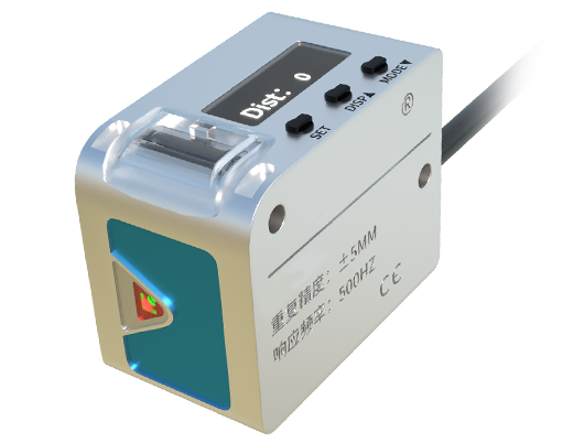
Modulation circuitry is frequently present for applications requiring noise immunity or distance measurement via phase-shift or amplitude modulation. This involves a modulation input signal (sine wave or digital) that is mixed with the DC bias current of the laser driver. A simple implementation might use a transistor in a common-emitter configuration, where the modulation signal is AC-coupled to the base, superimposing the varying signal onto the DC bias at the collector driving the laser diode. More advanced designs use dedicated laser driver ICs with separate modulation pins.
The optical path control, while partially mechanical, has electronic counterparts in the schematic. For sensors with adjustable focus or beam steering (e.g., using a galvanometer), the schematic will include motor driver circuits or galvanometer driver amplifiers. These receive low-voltage control signals and generate the higher current or voltage needed to precisely move optical elements.
Power supply design is integral. A clean, low-noise regulated voltage is required for the analog control circuits (op-amps, sensors) and the digital logic if a microcontroller is present. The schematic shows separate linear voltage regulators or switching converters with ample filtering (using capacitors and inductors) to prevent switching noise from interfering with the sensitive analog laser drive signals. Grounding and layout considerations, often noted on schematics as notes or separate layers, are crucial to prevent ground loops and electromagnetic interference (EMI).
A modern laser sensor transmitter schematic will also incorporate a microcontroller or digital signal processor (DSP). This block manages system initialization, monitors fault conditions (like over-temperature or open laser diode), handles communication interfaces (e.g., IO-Link, RS-485, Ethernet), and may implement advanced digital control algorithms for the driver and temperature control. The schematic details its connections: crystal oscillator circuit, programming/debugging interface, ADC channels reading various sensors, and GPIOs controlling other circuit blocks.
In conclusion, a laser sensor transmitter schematic is a symphony of analog precision, digital control, and power management. It transforms a basic electrical supply into a stable, controlled, and often intelligent source of coherent light. Understanding each block—from the robust constant-current driver and meticulous temperature stabilization to the optional modulation and embedded digital control—is essential for designing, troubleshooting, and applying these versatile sensors effectively in demanding industrial environments. The elegance of the design lies in its ability to maintain extreme optical stability from simple electrical inputs, a feat achieved through thoughtful electronic engineering captured in its schematic diagram.