In the realm of industrial automation and electrical control systems, proximity sensors are indispensable components. They provide non-contact detection of objects, enabling precise control, positioning, and safety functions. For electrical engineers and technicians, accurately interpreting and applying the correct electrical symbols for these sensors on schematic diagrams (schematics) and ladder logic diagrams is fundamental. This guide delves into the standard symbols, their variations, and practical considerations for proximity sensors in electrical documentation.
The foundation for most electrical symbols, including those for sensors, is established by international standards, primarily the International Electrotechnical Commission (IEC) standards (IEC 60617) and, in some regions, the older but still prevalent standards from the National Electrical Manufacturers Association (NEMA) or JIC (Joint Industrial Council). The IEC symbols are widely adopted globally due to their logical and functional representation.
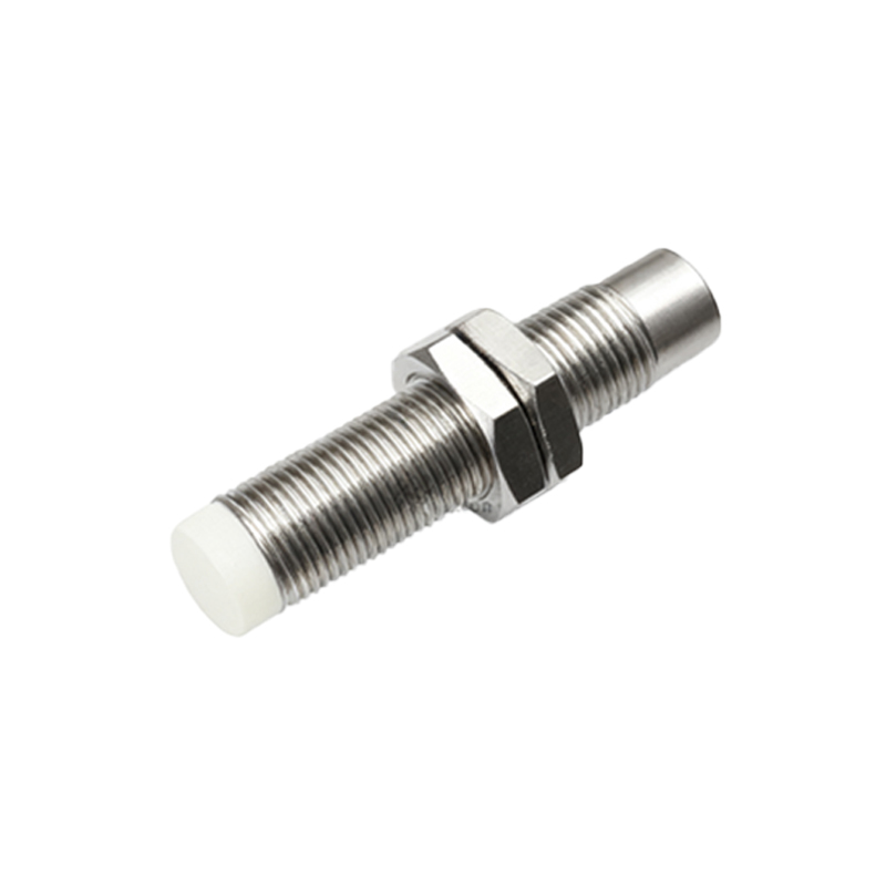
At its core, a proximity sensor symbol represents a switch operated by an external influence (the target object) rather than a manual actuator. The basic symbol is a circle, often referred to as the "operator" or "actuator" symbol, with a diagonal line through it. This circle is attached to the electrical contact symbols. The key differentiator lies in the graphic inside or adjacent to this circle, which indicates the sensing principle.
Common Proximity Sensor Symbols:
1. Inductive Proximity Sensor: This sensor detects metallic objects. Its IEC symbol features the standard circle with a diagonal line. Inside the circle, a series of horizontal lines or a stylized "coil" icon is drawn, representing the oscillator coil. The output is typically a solid-state switch (transistor), symbolized by a standard switch contact (NO or NC) with a small diamond shape nearby to denote a semiconductor output. The entire symbol is often labeled with "L+" and "L-" or "1" and "3" for the power supply connections, and the output terminal as "2" or "4".
2. Capacitive Proximity Sensor: Used for detecting both metallic and non-metallic materials (plastics, wood, liquids), its symbol is similar to the inductive type. The distinguishing feature is the graphic inside the circle: two parallel lines, resembling a capacitor plate. This directly signifies the capacitive sensing principle. Like inductive sensors, the output is shown as a semiconductor switch symbol.
3. Photoelectric Sensor (Photocell): While not always classified strictly as a "proximity" sensor, diffuse and retro-reflective modes function as such. The IEC symbol uses two diagonally arranged arrows pointing towards and away from a circle (representing the light emitter and receiver). It is often depicted as two separate symbols (a diode-like symbol for the emitter and a transistor-like symbol for the receiver) connected by a dashed line indicating the light beam. The output contact is shown accordingly.
4. Ultrasonic Proximity Sensor: The symbol incorporates a stylized representation of sound waves—concentric arcs emanating from the operator circle. This clearly differentiates it from optical or inductive types.
Output Configuration Representation:
The sensor's electrical output is crucial. Symbols must indicate:
Normally Open (NO) or Normally Closed (NC): The contact symbol itself shows this. An open contact is NO; a closed contact is NC in the non-actuated state.
PNP vs. NPN (Sourcing vs. Sinking): For DC 3-wire sensors, this is critical for PLC input compatibility. The symbol often doesn't visually show this difference; it is conveyed through the labeling of the output terminal (e.g., "PNP" written near the output, or the electrical schematic showing the load connected to positive or negative relative to the output transistor).
Analog Outputs: Sensors with 4-20mA or 0-10V outputs use a different symbol, typically a circle with the letters "A/O" or a specific signal waveform icon, connected to output terminals.
Practical Application in Schematics and Ladder Logic:
On a schematic, the sensor symbol is placed within the circuit, showing its power supply connections and how its output switch interfaces with the load (e.g., a PLC input module, relay coil). In ladder logic diagrams, the sensor's output contact is used as an input condition. It is represented as a standard contact symbol (--| |-- for NO, --|/|-- for NC) and is labeled with a unique address (e.g., I0.0, X1). The physical sensor type (inductive, capacitive) is usually detailed in a separate parts list or I/O schedule, not in the ladder logic rung itself.
Best Practices for Engineers:
Consistency is Key: Adhere strictly to one standard (IEC