Laser sensors are indispensable tools in modern industrial automation, offering high precision, non-contact measurement for tasks ranging from object detection and positioning to thickness gauging and defect inspection. However, their accuracy and reliability are heavily dependent on proper calibration and adjustment. Incorrect setup can lead to measurement errors, production downtime, and costly quality issues. This guide outlines the fundamental principles and step-by-step procedures for calibrating and adjusting common types of laser sensors, including triangulation, time-of-flight (ToF), and confocal displacement sensors.
The first critical step is understanding the sensor's datasheet and operational parameters. Key specifications include measuring range, resolution, repeatability, linearity, spot size, and response time. The operating environment must also be assessed. Factors such as ambient light, temperature fluctuations, dust, oil mist, and the target material's surface properties (color, reflectivity, texture) significantly influence sensor performance. For instance, a highly reflective surface can saturate the receiver, while a dark, absorbent surface may return a weak signal. Many modern sensors feature automatic teaching or learning functions to compensate for different surface conditions.
Mounting and mechanical alignment form the foundation of accurate sensing. Ensure the sensor is securely fixed to minimize vibration. The laser beam must be perpendicular to the target surface within the specified tolerance to avoid cosine error. For distance measurement sensors, any angular deviation will introduce a proportional error in the reading. Use precision mounting brackets and adjust the sensor's orientation while monitoring the output until the beam is optimally aligned. For applications involving moving targets, consider the beam's angle relative to the direction of motion.
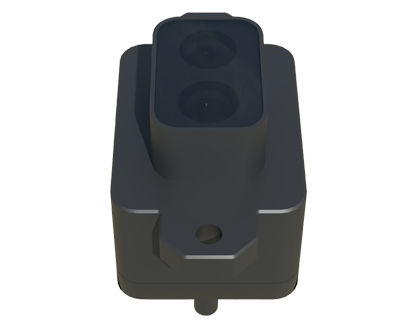
Electrical connection and signal configuration come next. Connect the sensor to a stable power supply, adhering to the specified voltage (typically 12-24V DC). Noise from machinery or variable frequency drives can interfere with sensor signals; using shielded cables and proper grounding is essential. Configure the output signal type—analog (e.g., 4-20mA, 0-10V), digital (e.g., NPN/PNP switching), or serial communication (e.g., RS-485, IO-Link)—to match the input requirements of your PLC or controller. Set the switching logic (light-on/dark-on) appropriately for your application.
The core adjustment process involves setting the measurement or detection window. For simple presence detection, teach the sensor the "background" state (no target) and the "object" state. The threshold is then set between these two values. For analog measurement sensors, a two-point calibration is often performed. First, place a reference target at the minimum measurement distance (or a known low value) and adjust the output to correspond to the minimum scale (e.g., 4mA or 0V). Then, place a target at the maximum distance (or known high value) and adjust the output to the maximum scale (e.g., 20mA or 10V). Some sensors allow for multi-point linearization to correct for non-linearity across the range.
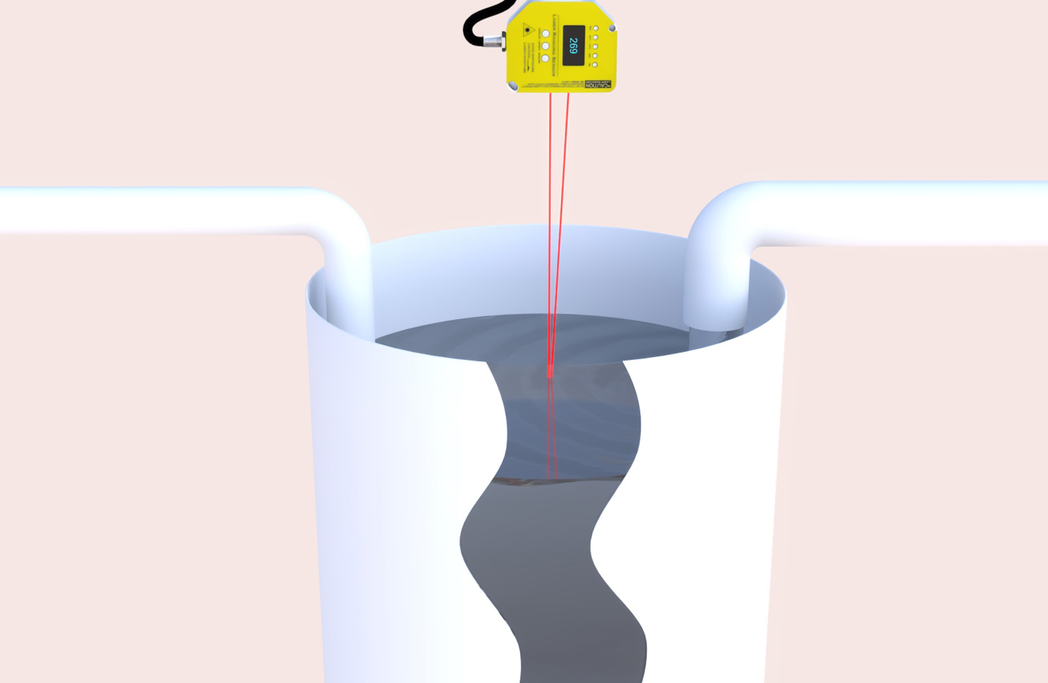
Fine-tuning is crucial. After initial calibration, test the sensor with multiple samples representing the expected variation in the production process. Observe the stability of the readings. Adjust the sensor's internal parameters if available: filtering can smooth out noise but may slow response time; the response delay or hysteresis setting can prevent chattering in edge detection. For challenging surfaces, adjust the receiver's gain or sensitivity. The goal is to achieve a stable, repeatable signal with a sufficient signal-to-noise ratio.
Finally, implement validation and maintenance routines. After adjustment, verify performance using certified calibration standards or gauge blocks. Document all settings. Establish a periodic recalibration schedule based on the sensor's criticality and environmental stress. Regularly clean the lens with appropriate materials to prevent buildup that attenuates the laser beam. Monitor long-term drift in the sensor's output.
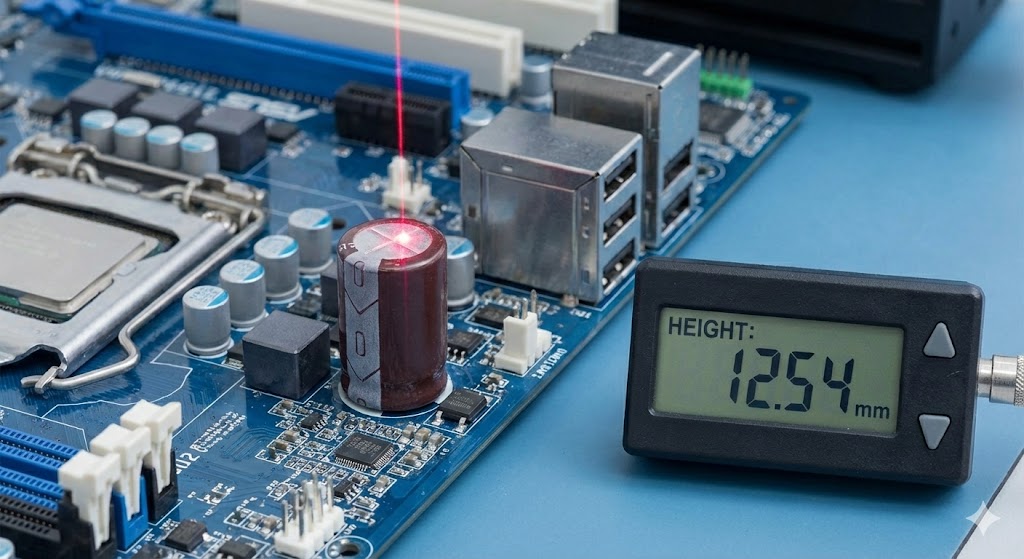
By following this systematic approach—understanding specifications, ensuring proper mounting, configuring electrical signals, performing precise calibration, and conducting ongoing maintenance—engineers can ensure laser sensors deliver their full potential of accuracy and reliability, thereby enhancing overall system performance and product quality in demanding industrial environments.