In industrial automation and control systems, proximity switch sensors are indispensable components for non-contact detection of metallic or, in some cases, non-metallic objects. Their reliability is paramount for ensuring operational safety, efficiency, and process continuity. However, a persistent challenge that engineers and maintenance personnel face is sensor interference, which can lead to erratic behavior, false triggering, or complete failure. This article delves into the common sources of interference for proximity switch sensors and outlines practical mitigation strategies.
The fundamental operating principle of most inductive proximity sensors involves generating a high-frequency electromagnetic field from an oscillator coil. When a metallic target enters this field, eddy currents are induced, causing a change in the oscillator's amplitude. This change is detected, processed, and converted into a switching signal. Capacitive sensors work on a similar principle but react to changes in capacitance caused by any material. This inherent sensitivity to electromagnetic phenomena makes them susceptible to various forms of interference.
The primary sources of interference can be categorized as follows:
1. Electromagnetic Interference (EMI): This is the most common culprit. Sources include variable frequency drives (VFDs) controlling motors, welding equipment, high-current switching relays and contactors, radio transmitters, and even other proximity sensors placed in close proximity. These devices generate strong, fluctuating electromagnetic fields that can couple into the sensor's circuitry or its connecting cables, inducing unwanted voltages.
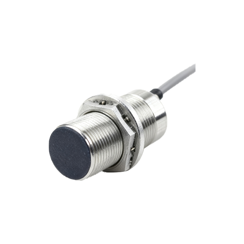
2. Electrical Noise on Power Lines: Noise and voltage spikes on the DC supply line, often originating from the switching of large inductive loads elsewhere on the same circuit, can disrupt the sensor's internal electronics. This can cause the sensor to reset, output a false pulse, or behave unpredictably.
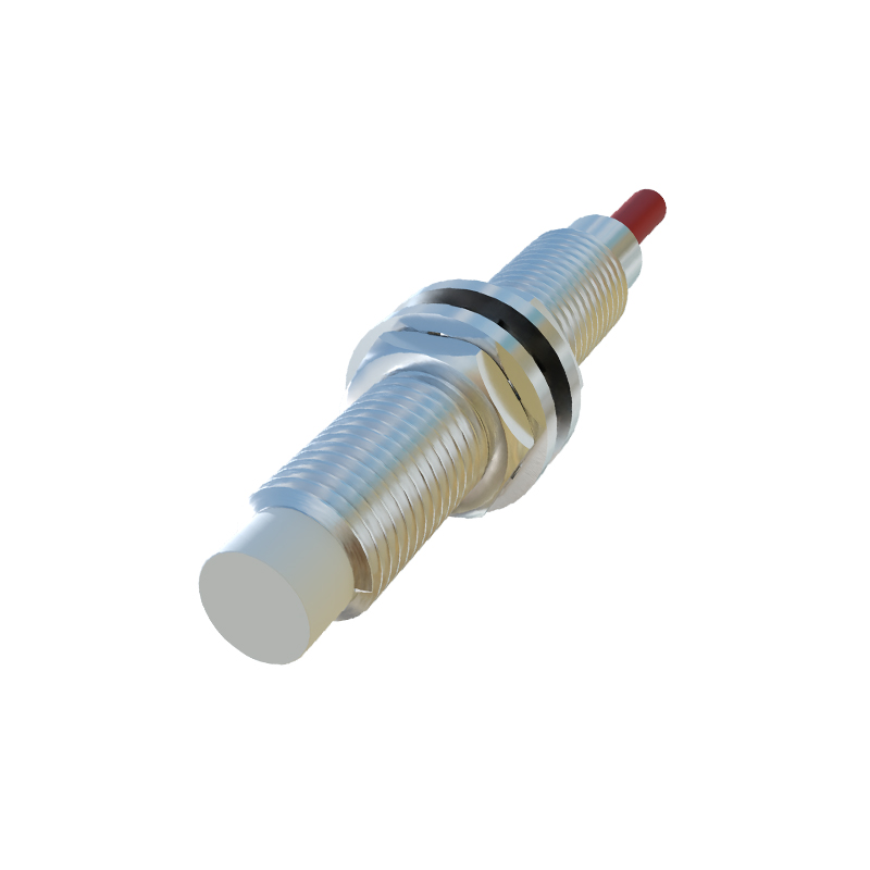
3. Mutual Interference (Sensor-to-Sensor): When multiple inductive proximity sensors are mounted too close to each other, their oscillating magnetic fields can interact. This crosstalk can cause sensors to activate each other or fail to detect their intended target reliably. The required separation distance depends on the sensor's diameter, sensing range, and mounting style (flush or non-flush).

4. Ground Loops: When a system has multiple ground paths at different potentials, current can flow through the sensor's ground wire or shielding. This ground loop current introduces noise into the signal path, leading to instability.
5. Environmental Factors: While not interference in the classic electrical sense, the presence of conductive dust, metal chips, or aggressive chemicals in the environment can alter the sensing field or damage the sensor face, mimicking interference symptoms.
Mitigation Strategies and Best Practices:
Addressing interference requires a systematic approach, starting from sensor selection and installation.
Proper Sensor Selection and Installation: Choose sensors with robust designs, often denoted by high EMI immunity ratings (e.g., 30V/m or higher). For inductive sensors, ensure the correct mounting (flush or non-flush) as specified. Maintain adequate lateral spacing between sensors—a general rule is to keep them at least two to three times the sensor diameter apart. For opposite mounting, increase the distance further.
Cabling and Wiring Practices: This is critical. Always use shielded cables for both power and signal lines. The cable shield must be grounded at only one end, typically at the controller or PLC side, to prevent ground loops. Keep sensor cables as short as possible and route them away from high-power cables (motors, welding leads, power feeders). A minimum separation of 20-30 cm is recommended. If crossing is unavoidable, do so at a 90-degree angle to minimize inductive coupling.
Power Supply Conditioning: Use a stable, regulated DC power supply dedicated to the sensors. Incorporate filtering at the power entry point. Ferrite cores or beads clamped around the sensor cable near the connector can be highly effective in suppressing high-frequency noise. In severe noise environments, consider using an isolating or filtered power supply module.
System Grounding: Establish a single-point, low-impedance ground reference for the entire control system. Ensure all cabinet panels, cable trays, and shields are bonded properly to this ground point to equalize potentials.
Utilizing Sensor Features: Many modern sensors come with built-in protection. Features like short-circuit protection, reverse polarity protection, and built-in surge suppressors enhance resilience. Some sensors offer adjustable switching hysteresis or time delays, which can help "debounce" the signal and ignore brief interference pulses.
Testing and Diagnostics: When interference is suspected, systematically isolate components. Temporarily power the sensor from a separate, clean battery to rule out power line noise. Disconnect and reconnect cables while monitoring the output. Use an oscilloscope to visualize noise on the signal line. Many PLCs and controllers have diagnostic tools to monitor signal stability.
In conclusion, while proximity switch sensors are inherently vulnerable to electromagnetic and electrical