Proximity sensors are ubiquitous in modern automation, playing a critical role in object detection without physical contact. Their structure is fundamentally designed to achieve this non-invasive sensing, and while designs vary by type, they share common architectural principles. This article delves into the core structural components and how they orchestrate to enable precise proximity detection.
At the heart of most proximity sensors lies four key structural blocks: the oscillator, the sensing coil or emitter, the detection circuit, and the output circuit. The oscillator generates a high-frequency electromagnetic field or light signal. This is channeled to the active face of the sensor via the sensing element. In an inductive proximity sensor, this is a coiled wire wound around a ferrite core, creating a precise electromagnetic field. In a capacitive sensor, it forms one plate of a capacitor. For photoelectric sensors, this component is a Light Emitting Diode (LED) or laser diode.
The structure of the sensing face is crucial. It is typically a flat, robust surface made of a material that allows the generated field or beam to pass through. For inductive sensors, this is often a wear-resistant plastic that doesn't interfere with the electromagnetic field. The target object, when it enters this active field, causes a detectable change. In inductive sensors, eddy currents are induced in conductive targets, dampening the oscillator's amplitude. Capacitive sensors react to changes in capacitance caused by any material, while photoelectric sensors detect the presence or absence of a reflected or broken light beam.
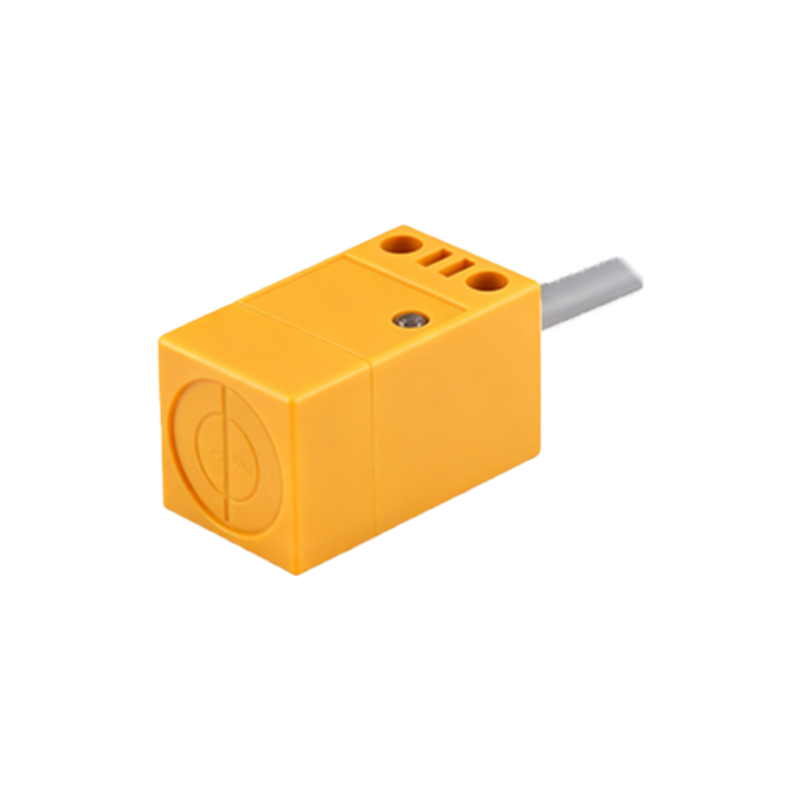
Internally, the detection circuit, often a Schmitt trigger or a specialized IC, continuously monitors the signal from the oscillator. Its structural design is focused on stability and noise immunity to prevent false triggering. When the change caused by the target reaches a predefined threshold, the detection circuit sends a signal to the output circuit.
The output circuit structure defines how the sensor communicates with the wider control system, such as a PLC. Common output configurations include NPN (sinking), PNP (sourcing), analog (4-20mA or 0-10V), or IO-Link for digital communication. This circuit is physically connected to the sensor's output terminals or connector. The entire assembly is housed in a rugged body, commonly cylindrical (threaded barrel) or rectangular, made from metal (like stainless steel for harsh environments) or high-grade plastic. This housing provides environmental protection (with IP ratings), mechanical strength, and often incorporates mounting features like threads or brackets.
The structural arrangement is meticulously designed for reliability. Shielding is a critical aspect. Shielded (flush-mountable) inductive sensors have a metallic band around the sensing coil, concentrating the field radially forward and allowing installation flush with metal surfaces. Unshielded sensors have a longer sensing range but require non-metallic surroundings. Similarly, photoelectric sensors may have housings with threaded lenses for focus adjustment or built-in alignment indicators.

In essence, the structure of a proximity sensor is a compact, optimized integration of electromagnetic or optical generation, precise detection electronics, and robust industrial packaging. Each component's design—from the coil winding density to the housing material—is tailored to the specific sensing technology and intended application, ensuring reliable, maintenance-free operation in diverse industrial settings. Understanding this structure is key to selecting the right sensor for detection range, target material, environmental conditions, and required output signal.