In the realm of industrial automation and electronic design, capacitive proximity sensors play a pivotal role in non-contact detection of objects, leveraging changes in capacitance to sense presence. A fundamental aspect of integrating these sensors into schematics or system diagrams is comprehending their circuit symbols, which convey critical functional information at a glance. Unlike simpler passive components, the symbols for capacitive proximity sensors encapsulate both the sensing principle and electrical connectivity, adhering to international standards such as IEC 60617 to ensure universal readability among engineers and technicians.
Typically, the circuit symbol for a capacitive proximity sensor comprises a capacitor-like representation—two parallel lines indicating plates—combined with additional graphical elements to denote its active sensing nature. One common variant includes the capacitor symbol enclosed within a circle, signifying the sensor housing or integrated unit, with terminals marked for power supply, ground, and output signals. The output may be depicted as a switch symbol (like a normally open or normally closed contact) adjacent to the capacitor, illustrating the sensor's ability to trigger based on capacitance changes. For instance, a line extending from the capacitor to a transistor symbol might indicate a solid-state output, common in modern sensors for switching loads.
The symbol often incorporates arrows or dashed lines radiating from the capacitor plates, representing the electric field generated by the sensor. This highlights its capability to detect objects through dielectric variations, even non-metallic materials like plastics or liquids. In detailed schematics, annotations may specify parameters such as sensing range, operating voltage (e.g., 10-30 V DC), and output type (PNP/NPN). Engineers must interpret these symbols accurately to ensure proper wiring and compatibility with controllers like PLCs, avoiding issues like false triggering or inadequate response times.
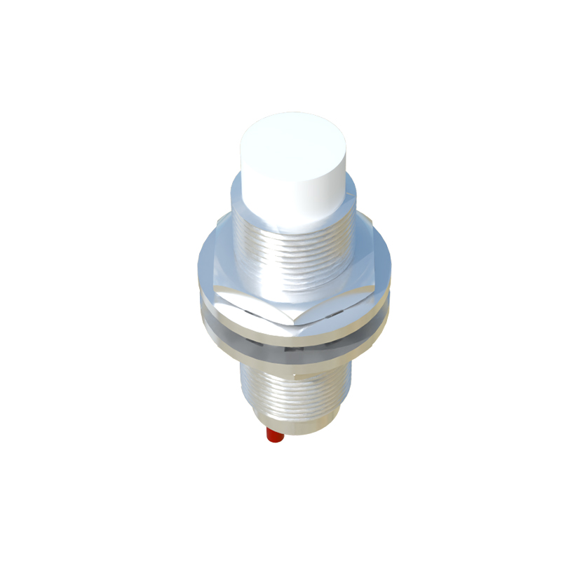
Moreover, variations exist based on sensor configurations. Two-wire sensors, which combine power and output in a single loop, might use a simplified symbol with fewer terminals, while three-wire or four-wire versions show distinct connections for supply, output, and sometimes a separate ground. Advanced symbols for analog-output capacitive sensors include a wave-like icon to signify continuous signal variation proportional to distance. Understanding these nuances is essential for designing circuits that meet safety and efficiency standards, particularly in harsh environments where factors like humidity or temperature can affect performance.
In practice, referencing manufacturer datasheets alongside standard symbols is crucial, as some companies add proprietary markings. However, the core symbolism remains rooted in depicting capacitance-based detection. Mastery of these symbols not only aids in schematic creation but also facilitates troubleshooting and system documentation, fostering seamless communication across global engineering teams. As technology evolves, symbols may adapt to include digital communication interfaces like IO-Link, but the foundational representation will continue to emphasize the sensor's capacitive essence.
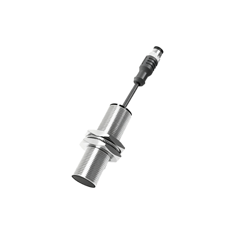
Overall, the circuit symbols for capacitive proximity sensors serve as a concise visual language, bridging theoretical principles with practical application. By decoding these symbols, professionals can optimize sensor deployment for tasks ranging from object counting to level sensing, enhancing automation reliability. Always verify symbol interpretations against industry norms to maintain design integrity and operational safety in electrical projects.