In industrial automation and electrical engineering, proximity sensors are widely used for detecting the presence or absence of objects without physical contact. While primarily known for their sensing capabilities, certain types of proximity sensors, especially inductive and capacitive models, involve voltage measurement in their operation or troubleshooting. Understanding how to measure voltage with these sensors is crucial for ensuring system reliability, diagnosing faults, and optimizing performance. This article provides a detailed guide on voltage measurement techniques for proximity sensors, adhering to industry standards and safety protocols.
Proximity sensors typically operate on DC or AC power supplies, with common voltage ranges from 10-30V DC or 20-250V AC. Voltage measurement is essential during installation, maintenance, and when issues like false triggers or sensor failures occur. To measure voltage effectively, follow these steps:
1. Safety First: Before any measurement, ensure the system is de-energized if possible, or use appropriate personal protective equipment (PPE) such as insulated gloves and goggles. Verify that your multimeter or voltmeter is rated for the expected voltage and in good condition.
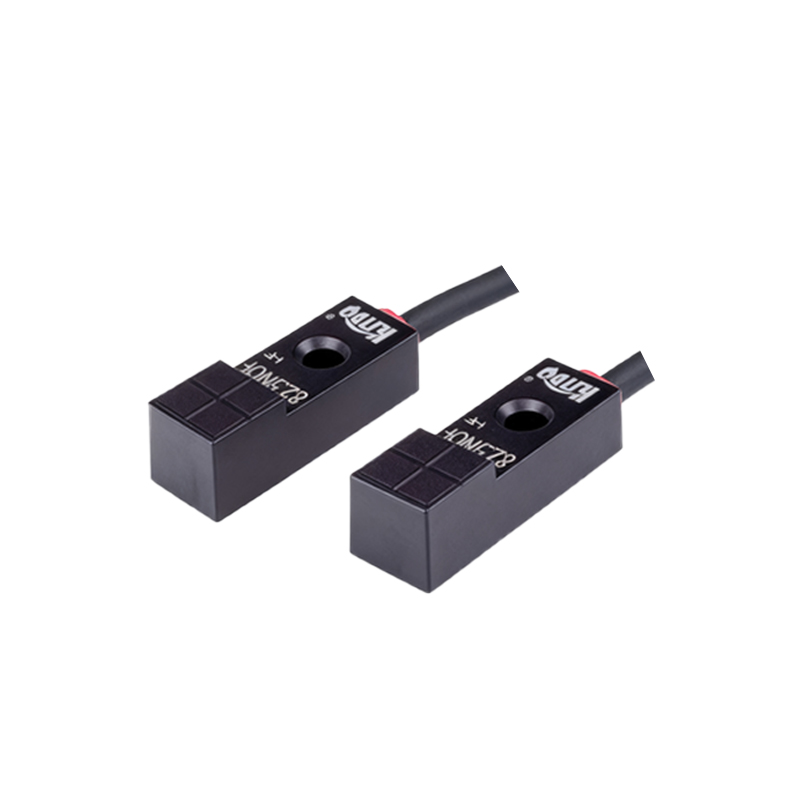
2. Identify Sensor Type and Wiring: Proximity sensors generally have three wires: brown (positive), blue (negative), and black (output). For DC sensors, the brown wire connects to the positive supply, blue to negative, and black to the load. AC sensors may have different color codes, so refer to the datasheet. Voltage measurement involves checking the supply voltage at the sensor terminals and the output voltage signal.
3. Measure Supply Voltage: Set your multimeter to the correct voltage range (DC or AC). Connect the probes to the brown and blue wires while the sensor is powered. A stable reading within the specified range (e.g., 24V DC ±10%) indicates proper power supply. Fluctuations or deviations can lead to sensor malfunction and require investigation into the power source or wiring.
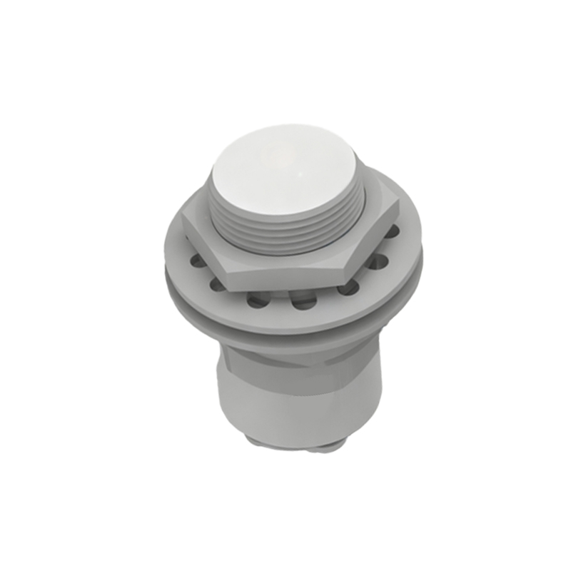
4. Measure Output Voltage: For sensors with voltage output (e.g., PNP or NPN types), measure between the black wire and the negative (blue) wire. In a no-detection state, the output should be near 0V for NPN or supply voltage for PNP. When an object is detected, the voltage switches accordingly. This helps verify sensor logic and response.
5. Check for Voltage Drops and Noise: Use the multimeter to measure voltage along the wiring path, especially over long distances. Excessive voltage drops due to resistance can impair sensor performance. Additionally, measure for electrical noise or interference, which may appear as erratic voltage readings, by monitoring the supply lines with an oscilloscope if available.
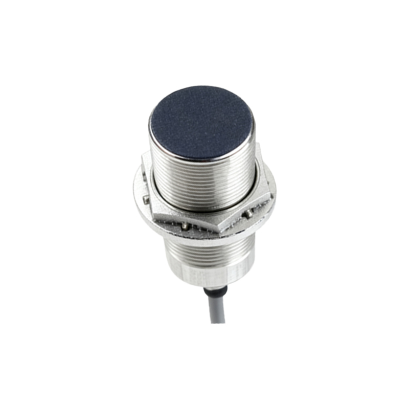
6. Troubleshooting Common Issues: If voltage measurements are abnormal, consider factors like short circuits, open wires, or incompatible loads. For instance, a sensor output stuck at high voltage might indicate a wiring fault or damaged internal components. Always cross-reference with manufacturer guidelines.
Advanced techniques include using data loggers to monitor voltage trends over time, which aids in predictive maintenance. In systems with multiple sensors, ensure consistent voltage levels to avoid cascading failures. Remember that some proximity sensors, like analog versions, output a variable voltage proportional to distance, requiring precise measurement for calibration.
In summary, voltage measurement for proximity sensors is a fundamental skill that enhances operational efficiency and reduces downtime. By following systematic procedures and prioritizing safety, engineers can maintain robust automation systems. Regular voltage checks, combined with sensor datasheets and industry best practices, form the backbone of effective electrical maintenance.