Proximity sensors are critical components in industrial automation, providing non-contact detection of metallic or non-metallic objects. However, like any electronic device, they can experience failures that disrupt production lines. This guide offers a systematic troubleshooting approach with clear diagrams to help engineers quickly diagnose and resolve common proximity sensor issues.
First, understand the basic types: inductive sensors detect metals, capacitive sensors detect various materials including liquids, and ultrasonic sensors use sound waves. Each type has unique failure modes. Start troubleshooting by verifying power supply. As shown in Diagram 1, use a multimeter to check voltage at the sensor terminals. Ensure it matches the sensor's rated voltage (typically 10-30V DC or 90-250V AC). Low voltage may indicate power supply issues or excessive cable length causing voltage drop.
Next, inspect the sensor's installation. Diagram 2 illustrates proper mounting: maintain correct sensing distance (usually 0.8-1.5 times the rated sensing distance), avoid metal-to-metal contact for inductive sensors, and ensure no obstructions block the sensing face. Misalignment is a common problem—use alignment tools to verify the target passes centrally through the sensing field.
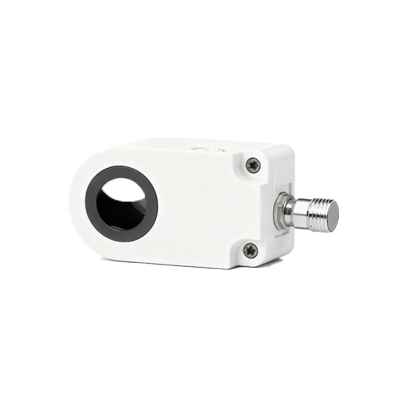
For false triggering, refer to Diagram 3 showing environmental interference sources. Electrical noise from motors or frequency drives can cause erratic operation. Implement shielding by using twisted-pair cables, grounding the shield at the controller end, and installing ferrite cores near the sensor. For capacitive sensors, humidity or material buildup on the face may trigger false detects—clean regularly with appropriate solvents.
When a sensor fails to detect, perform the output test in Diagram 4. Connect an LED test probe to the output wire. If the LED lights when a target is present but the PLC receives no signal, the issue may be a broken wire or faulty PLC input. If the LED doesn't light, the sensor may be damaged. For 3-wire sensors, check wiring: brown wire to positive, blue to negative, black is the output. For 2-wire AC sensors, ensure correct polarity if they're DC-polarized types.
Temperature effects are shown in Diagram 5. High ambient temperatures can reduce sensing distance or cause permanent damage. Verify the sensor's temperature rating matches the environment. In cold conditions, condensation may form—use sensors with appropriate IP ratings (IP67 or higher for wet environments). Thermal expansion can also shift mounting positions over time.
Diagnose sensing distance reduction using Diagram 6. Over time, sensing ranges may decrease due to component aging or dirt accumulation. Test with a standard target (usually a square of mild steel for inductive sensors). If the detection distance is less than 80% of the rated distance, replace the sensor. For capacitive sensors, recalibrate the sensitivity potentiometer if accessible.
Finally, Diagram 7 presents a decision tree for systematic troubleshooting: Start with power check, proceed to output verification, then environmental factors, and end with mechanical inspection. Document all findings—this helps identify recurring issues and optimize maintenance schedules.
Always consult the manufacturer's datasheet for specific testing procedures. Many modern sensors have diagnostic LEDs that flash error codes—refer to the manual for interpretation. When replacing sensors, ensure the new unit has identical electrical characteristics and mounting dimensions to avoid compatibility issues.
Preventive maintenance includes regular cleaning of sensing faces, checking cable integrity, and verifying mounting stability. Keep spare sensors calibrated and ready for quick replacement to minimize downtime. With these troubleshooting steps and diagrams, engineers can maintain optimal sensor performance and ensure reliable automation system operation.