Proper installation of proximity sensors is critical for ensuring reliable operation in industrial automation systems. This comprehensive video guide demonstrates best practices for mounting, wiring, and configuring inductive and capacitive proximity switches in various applications.
Before beginning installation, always verify the sensor specifications match the application requirements. Check the sensing distance, output type (PNP/NPN), voltage rating, and environmental protection rating (IP67 or higher for harsh conditions). Ensure the power supply is disconnected during installation to prevent electrical hazards.
Mounting proximity sensors requires attention to mechanical alignment and clearance. For cylindrical sensors, use appropriate mounting brackets to secure the body while maintaining the recommended sensing range. Avoid mounting metal objects within the sensing field that could cause false triggers. In vibrating environments, consider using vibration-resistant brackets and locknuts. Maintain a minimum clearance of twice the sensor diameter between adjacent sensors to prevent mutual interference.
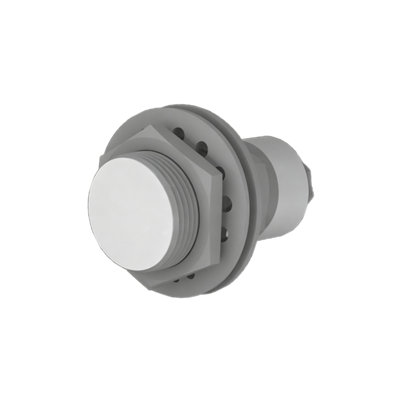
Wiring connections must follow the manufacturer's diagram precisely. For 3-wire DC sensors, distinguish between PNP (sourcing) and NPN (sinking) configurations. Use shielded cables in electrically noisy environments and ground the shield at the controller end. Keep signal cables separated from power lines by at least 200mm to minimize electromagnetic interference. For long cable runs exceeding 50 meters, verify voltage drop calculations to ensure proper sensor operation.
Configuration involves setting sensitivity and response time. Many modern sensors feature teach-in functions for easy adjustment. Test the installed sensor by moving the target object through its sensing path while monitoring the output indicator LED. For metallic targets, ensure the target material and size meet the sensor's specifications—carbon steel typically provides the longest sensing distance, while aluminum and copper require reduced ranges.
Maintenance tips include regular cleaning of sensing faces from dust or oil buildup, checking mounting hardware for loosening, and verifying electrical connections annually. Common installation errors to avoid include incorrect gap setting, improper target material selection, and inadequate environmental protection.
This video guide illustrates both flush-mounted and non-flush mounting techniques for different sensing profiles. Flush-mounted sensors can be installed in metal without affecting performance, while non-flush models offer longer ranges but require careful positioning. The demonstration includes real-world examples from conveyor systems, robotic cells, and machine tool applications.
By following these standardized procedures, technicians can maximize sensor lifespan, reduce false triggers, and maintain optimal system performance. Always consult the specific manufacturer's documentation for model-specific requirements and safety guidelines.