In industrial automation and precision measurement, laser sensors are indispensable components, renowned for their high accuracy, fast response, and non-contact operation. Proper wiring is fundamental to ensuring these sensors function reliably within a control system. This guide provides detailed wiring diagrams and explanations for several prominent laser sensor families, adhering to standard electrical engineering practices.
A typical laser sensor features several key terminals: power supply (Vcc and GND), output signal (NPN/PNP open collector or push-pull), and sometimes auxiliary lines for teach-in, synchronization, or diagnostic functions. The most common power configuration is 10-30V DC. Incorrect voltage application is a primary cause of sensor failure.
Model A: XYZ Corp. LRS-2000 Series (Diffuse Reflective Type)
This series often employs a 4-wire system.
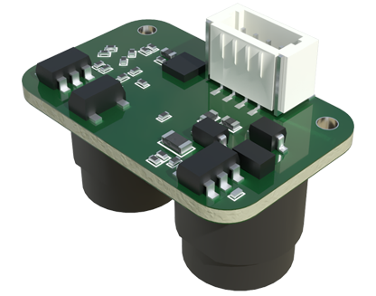
* Brown Wire: Connect to DC+ (10-30V).
* Blue Wire: Connect to DC- (0V/Ground).
* Black Wire: NPN Normally Open (NO) output. This wire switches to GND when an object is detected. It connects to the PLC's digital input card configured for NPN sinking input.
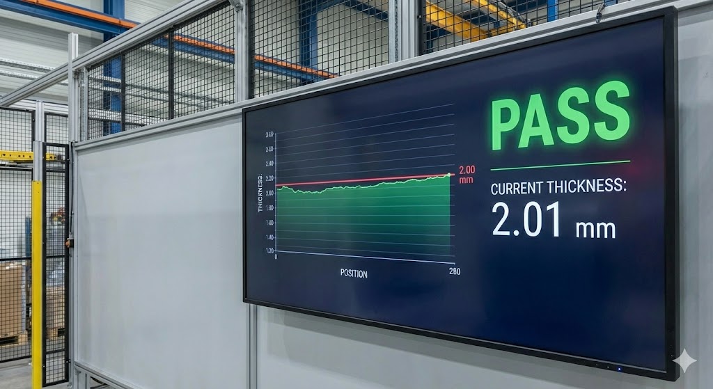
* White Wire: NPN Normally Closed (NC) output. This wire is at GND potential when no object is present and opens upon detection.
A 1kΩ pull-up resistor to Vcc may be required on the output lines depending on the PLC input characteristics. Always refer to the datasheet for the specific LRS-2000 variant.
Model B: ABC Inc. LDS-500 Series (Through-beam Type)
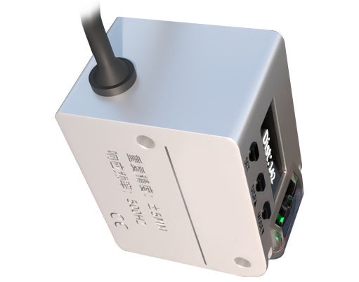
Through-beam sensors consist of separate transmitter and receiver units. The transmitter wiring is simple: typically Red to V+, Black to V-. The receiver unit has more complex wiring for its output.
* Transmitter (Tx): Red to +24V, Black to 0V.
* Receiver (Rx): Brown to +24V, Blue to 0V. The output is often a PNP configuration.
* Black Wire (Rx): PNP NO output. This wire switches to +24V when the beam is broken (object detected). It connects to a PLC input card configured for PNP sourcing input.
* White Wire (Rx): Teach-in input. Momentarily connecting this wire to +24V can trigger calibration routines.
Shielded cables are highly recommended for both units, with the shield grounded at the control panel to minimize electrical noise interference, which is critical for long-range beam integrity.
Model C: DEF Technologies LMS-100 (Background Suppression Sensor)
These sensors often feature analog output (0-10V or 4-20mA) in addition to a digital switch output.
* Power: Pin 1 (+V), Pin 2 (GND).
* Digital Output: Pin 3 (PNP NO/NC configurable via push-button).
* Analog Output: Pin 4 (4-20mA signal proportional to distance). The analog wire connects to a dedicated analog input module. The 4-20mA loop requires a precision resistor (e.g., 250Ω) at the PLC input to convert the current to a voltage signal.
For the 4-20mA output, ensure the loop power is supplied by the sensor itself or externally as specified. Incorrect analog wiring leads to erroneous readings.
General Wiring Best Practices:
1. Disconnect Power: Always isolate power before making connections.
2. Use Correct Wire Gauge: 18-22 AWG stranded wire is typical for signal and low-power lines.
3. Secure Connections: Employ ferrules on stranded wires for screw terminals to prevent fraying and short circuits.
4. Routing: Separate sensor cables from high-voltage AC power lines and motor drives by at least 20cm to avoid inductive coupling and noise. Use conduit or cable trays.
5. Protection: Incorporate appropriate fuses (e.g., 2A slow-blow) in the V+ line near the power supply. For outputs driving inductive loads like relays, use flyback diodes.
6. Grounding: Establish a single-point, robust earth ground for the entire system. Connect cable shields to this ground at the control panel end only, avoiding ground loops.
Troubleshooting Tips:
* No Power/No LED: Verify voltage at sensor terminals with a multimeter. Check polarity.
* Erratic Output: Likely electrical noise. Verify shield grounding, increase separation from noise sources, or install a ferrite core near the sensor connector.
* Output Stays On/Off: Check sensing mode (NO/NC). Verify the output load (PLC input impedance) is within sensor specifications. Test by substituting with a known-good load like a 10kΩ resistor and LED.
Understanding and meticulously following the manufacturer's wiring diagram is non-negotiable for system integrity. While the principles are consistent, pinouts, output types (NPN vs. PNP), and auxiliary functions vary significantly between models and manufacturers. Always consult the official installation manual for the specific part number before proceeding with installation. Proper wiring ensures not only optimal performance but also enhances the operational lifespan of these critical sensing components.