In industrial automation and control systems, proximity sensors are indispensable components for detecting the presence or absence of objects without physical contact. Their reliability hinges on one critical parameter: the correctly set sensing distance. This distance, often referred to as the nominal sensing distance (Sn), is not a fixed value to be taken for granted. It is influenced by a multitude of factors including the sensor type, target material, size, and environmental conditions. Improper setting can lead to false triggers, missed detections, and ultimately, system downtime. This guide provides a systematic, engineering-focused approach to accurately setting and optimizing the sensing distance for various proximity sensor technologies.
The first step is a fundamental understanding of the sensor technology in use. Inductive proximity sensors detect metallic objects. Their nominal sensing distance (Sn) is typically defined for a standard target of mild steel (Fe360) with a side length equal to the sensor's diameter or three times the Sn, whichever is greater. For non-ferrous metals like aluminum, brass, or copper, the effective sensing distance is reduced. A correction factor, usually provided in the datasheet, must be applied. For instance, sensing aluminum might require multiplying the Sn by a factor of 0.3 to 0.5. Capacitive sensors, used for detecting both metallic and non-metallic materials (plastics, wood, liquids), are highly sensitive to the target's dielectric constant. Their sensing distance is adjustable via a potentiometer and is easily influenced by ambient humidity or contaminants on the sensor face. Ultrasonic sensors measure the time-of-flight of sound waves and are suitable for various materials and longer ranges. Their setup involves configuring both the switching threshold and often a "window" for distance discrimination. Photoelectric sensors, while not strictly "proximity" in the same sense, offer diffuse, retro-reflective, and through-beam modes for non-contact detection, with sensing distances heavily dependent on target color, reflectivity, and surface finish.
Before installation and adjustment, meticulous preparation is paramount. Always consult the manufacturer's datasheet. This document contains the essential specifications: nominal sensing distance (Sn), operating voltage, output type (PNP/NPN, NO/NC), housing material, temperature ratings, and importantly, the recommended target size and material. Ensure the power supply matches the sensor's requirements. For adjustable sensors, locate the sensitivity potentiometer or teach-in button. The installation environment must be considered. Inductive sensors require a non-metallic mounting area to prevent flanking interference. Maintain a minimum clearance between multiple sensors to avoid mutual interference. For all sensors, ensure the target approaches the active sensing face perpendicularly for maximum and repeatable detection.
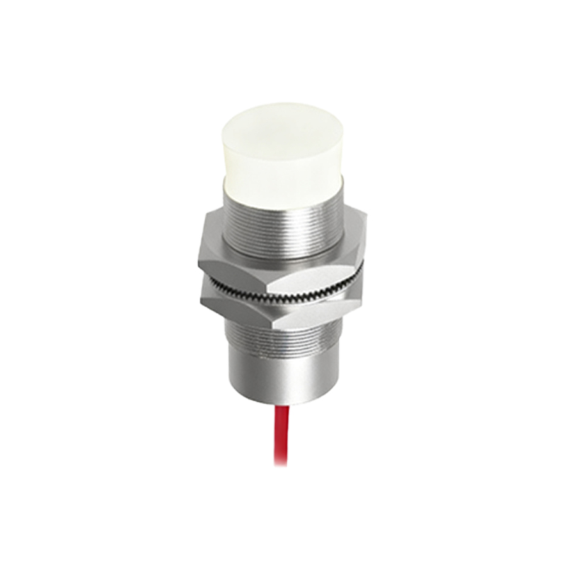
The core procedure for setting the distance involves a methodical approach. For sensors with a fixed sensing distance (often cheaper inductive models), the rule is simple: install the sensor so that the target comes within 70% to 80% of the rated Sn under all tolerance conditions (mechanical play, thermal expansion). This built-in safety margin, or "derating," accounts for supply voltage fluctuations, temperature drift, and part wear. For sensors with a sensitivity adjustment potentiometer, use the following best practice:
1. Mount the sensor in its final position.
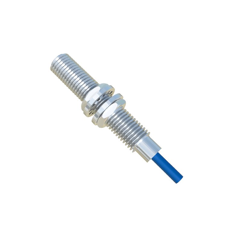
2. Bring the standard target (as per datasheet) to the desired maximum detection point.
3. Slowly rotate the potentiometer until the output indicator (usually an LED) just switches state (ON or OFF).
4. Move the target away and confirm the output returns to its normal state.
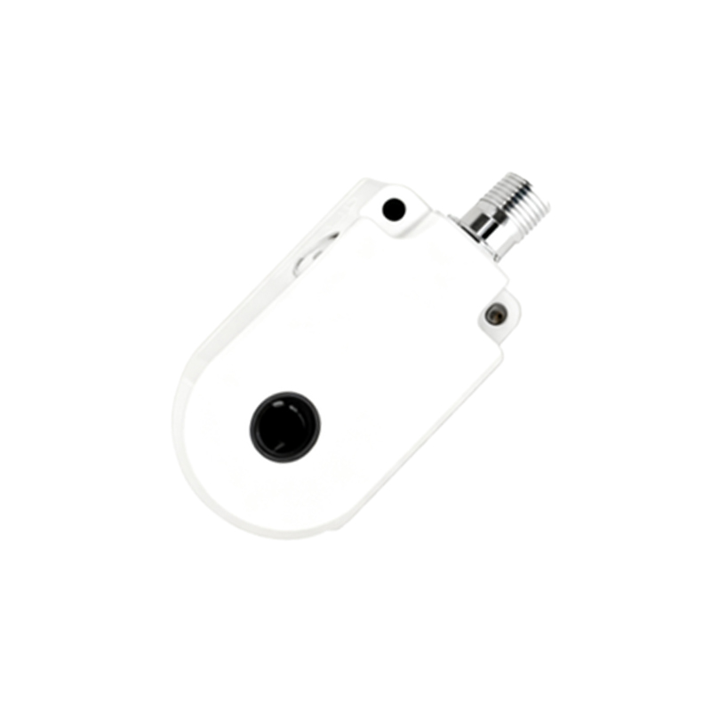
5. Re-introduce the target and verify stable switching. For critical applications, repeat this process at the minimum and maximum operating temperatures if possible.
Fine-tuning and troubleshooting are where engineering expertise shines. If a sensor is unstable (chattering), it is likely operating at the very edge of its sensing range. Slightly reduce the sensitivity or increase the gap between the sensor and target. For capacitive sensors, instability often points to environmental interference. Adjust the sensitivity to the lowest reliable level and consider using a shielded model or a separate guard electrode. For inductive sensors detecting small or thin targets, you may need to increase sensitivity. Remember that all sensors have hysteresis—a difference between the switch-on and switch-off points. This is a designed feature to prevent oscillation and should not be "adjusted out." Always verify the set distance under real-world operating conditions, including the presence of coolant, dust, or vibration.
Finally, rigorous validation is non-negotiable. After setting, perform a series of tests. Check for reliable detection across hundreds of cycles. Test with the actual production part, not just a perfect standard target. Verify the sensor does not trigger on nearby non-target objects (e.g., a machine frame or passing fixture). Document the final potentiometer position or mounting distance for future maintenance. Implementing these steps transforms proximity sensor setup from a guessing