A non-responsive sensor on a laser cutting machine is a critical issue that can halt production, compromise safety, and lead to costly material waste. As an experienced electrical engineer in the industrial automation field, I will guide you through a systematic, professional approach to diagnosing and resolving this common yet complex problem. Understanding that sensor failure is rarely an isolated event but often a symptom of a broader system interaction is key to effective troubleshooting.
The first step is always to ensure operator safety and machine security. Power down the laser cutter according to the manufacturer's lockout/tagout (LOTO) procedures. Visually inspect the sensor in question. Is it a proximity sensor, a capacitive sensor for material detection, a photoelectric safety interlock, or a rotary encoder for motion feedback? Identify the type—inductive, capacitive, optical—as this dictates the diagnostic path. Look for obvious physical damage: cracked housings, bent mounting brackets, or contamination from metal dust, smoke residue, or coolant. Laser cutting environments are harsh; optical lenses and sensor faces can become coated, blocking signals.
Once a visual inspection is complete, the core of electrical troubleshooting begins. With the machine safely powered, use a multimeter to check the power supply to the sensor. Refer to the machine's electrical schematic. Most industrial sensors operate on 12-24V DC. Verify that the correct voltage is present at the sensor's terminals. A low or absent voltage points to a faulty power supply, a blown fuse, or a broken wire. Next, check the sensor's output signal. For a digital PNP/NPN sensor, monitor the output terminal with your meter set to DC voltage. Actuate the sensor (e.g., place metal near an inductive prox). The output should switch from either 0V to +Vcc (for PNP) or +Vcc to 0V (for NPN). No change indicates a failed sensor or incorrect wiring.
Wiring issues are a frequent culprit. Perform continuity tests on the sensor's cables, checking for breaks, especially at stress points like cable glands and connectors. Don't forget to check the shield/ground connection. Poor grounding can cause erratic behavior or complete non-responsiveness due to electrical noise interference, which is prevalent from the laser's high-voltage power supplies and rapid switching drivers. Ensure all connections at the PLC (Programmable Logic Controller) or I/O module are secure. A loose terminal block can mimic a sensor failure.
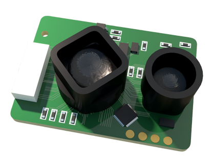
Environmental factors are often overlooked. Strong ambient light can swamp a photoelectric sensor. Magnetic fields from large motors can affect inductive sensors. Ensure the sensor is not mounted too far from its target, exceeding its specified sensing range. For material detection sensors, a change in material type (e.g., from aluminum to brass) can affect performance if the sensor isn't tuned or is of the wrong type.
If power, wiring, and environment are confirmed good, the problem may lie downstream. The sensor signal travels to an input card on the PLC. Use the machine's HMI (Human-Machine Interface) to monitor the status of that specific input address. If the sensor is actuating but the PLC input does not toggle, the issue could be a failed input channel. Try swapping the sensor's wire to a known-working input (of the same type) to confirm. Alternatively, the problem could be in the logic itself. A software bug, a changed parameter, or a disabled rung in the ladder logic could make the system ignore a perfectly functional sensor. Consulting the machine's software documentation is essential here.
Finally, consider mechanical misalignment. A safety door interlock sensor might not align if the door is warped. A rotary encoder's coupling might be loose, causing it to miss counts. A material height sensor might be obstructed. Always verify the mechanical relationship between the sensor and its target.
In summary, a methodical approach is paramount: Safety First, Visual Inspection, Electrical Verification (Power, Output, Wiring), Environmental Check, and Downstream Analysis (PLC, Software). Documenting your findings and solutions is crucial for future maintenance. While replacing a faulty sensor is sometimes the answer, a comprehensive troubleshooting process often reveals simpler, less expensive root causes, minimizing machine downtime and maintaining peak operational efficiency.