In the realm of automation, consumer electronics, and industrial safety, proximity sensors are indispensable components. They detect the presence or absence of an object within a specified range without physical contact. However, the true potential of these sensors is unlocked through their interface—the critical bridge that translates a physical detection event into a usable electrical signal for a control system. Understanding proximity sensor interfaces is fundamental for engineers, technicians, and hobbyists aiming to implement reliable and efficient sensing solutions.
At its core, a proximity sensor interface handles the communication between the sensor element and the host controller, such as a PLC (Programmable Logic Controller), microcontroller, or industrial computer. The interface manages signal conditioning, output type, wiring, and sometimes basic logic. The choice of interface depends heavily on the sensor's operating principle, the application environment, and the requirements of the control system.
The most fundamental distinction in proximity sensor interfaces lies in their output type. The two primary categories are digital and analog outputs. Digital output sensors provide a simple on/off signal. When a target object is within the detection range, the output switches state—either from a high voltage to a low voltage (NPN or sinking output) or from a low voltage to a high voltage (PNP or sourcing output). This binary signal is ideal for applications like object counting, limit switching, or part presence verification. Selecting between NPN and PNP is crucial and must match the input circuit of the controller to ensure proper operation.
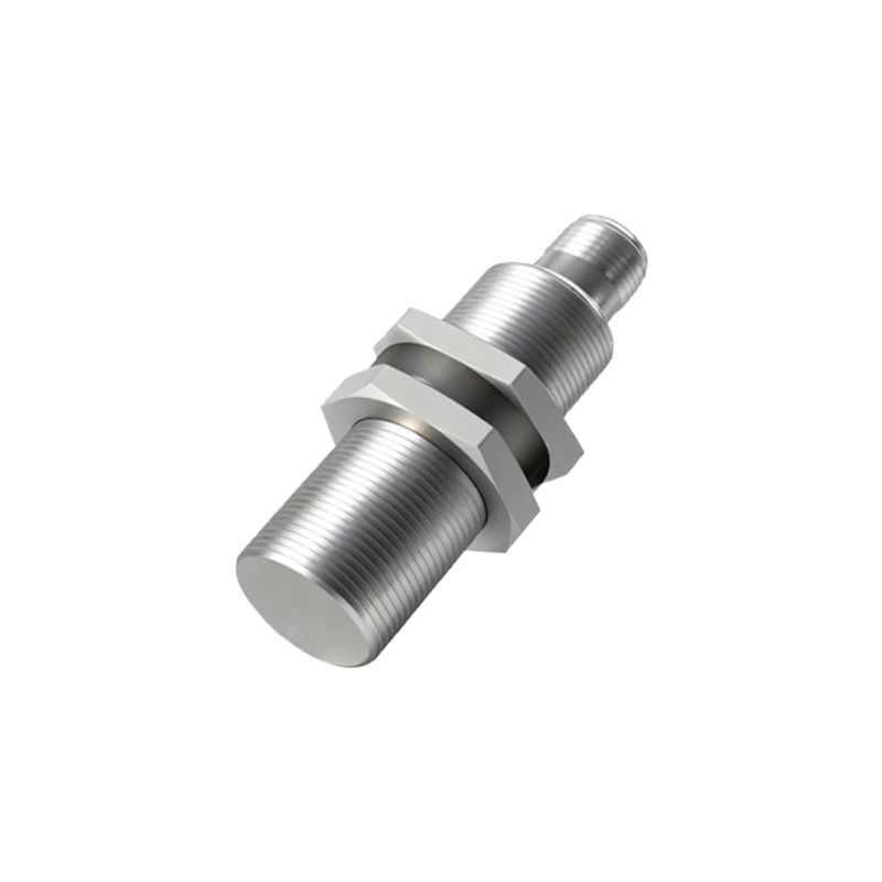
Analog output sensors, on the other hand, provide a continuous signal that varies in proportion to the distance to the target. Common analog signals include 0-10V DC, 4-20mA current loops, or increasingly, digital protocols over analog-like wiring. This continuous data allows for precise distance measurement, thickness monitoring, or controlling the position of an actuator. The 4-20mA interface is particularly valued in industrial settings for its robustness over long distances and inherent ability to indicate a wire break (current falls to 0mA).
Beyond simple voltage outputs, modern proximity sensors often incorporate more sophisticated interface protocols. These are especially common in complex machinery and Industry 4.0 applications. IO-Link is a prime example. It is a point-to-point serial communication protocol that transforms a standard digital sensor into an intelligent device. Over a standard 3-wire cable, IO-Link not only transmits the switching signal but also a wealth of digital data. This includes device parameters, process values, diagnostic information (like temperature warnings or contamination alerts), and allows for remote configuration and parameterization. This digital interface greatly simplifies wiring, troubleshooting, and asset management.
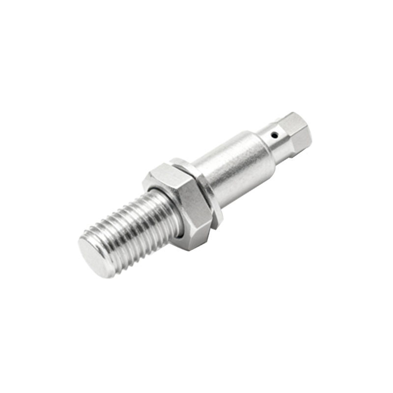
Another critical aspect of the interface is the physical connection and wiring scheme. Most industrial proximity sensors use quick-disconnect connectors or pre-wired cables. Standard color coding (brown for +V, blue for 0V or common, and black for the output signal) is almost universal. For sensors in harsh environments, interfaces must be designed to be sealed (e.g., IP67 rating) and resistant to electromagnetic interference (EMI). Shielding of cables is often necessary when installing sensors near motors, variable frequency drives, or high-current lines to prevent false triggering.
Integrating a proximity sensor into a system involves several key steps. First, select the sensor type (inductive, capacitive, photoelectric, ultrasonic) based on the target material and environmental conditions. Next, choose the appropriate interface: a simple PNP/NPN digital output for a basic on/off task, an analog output for distance-proportional control, or a smart IO-Link interface for data-rich applications and easy maintenance. The power supply voltage (commonly 10-30V DC) must match both the sensor and the controller input. Finally, proper mounting, alignment, and environmental protection are essential for reliable operation. Always refer to the manufacturer's datasheet for specific wiring diagrams, load specifications, and timing characteristics.
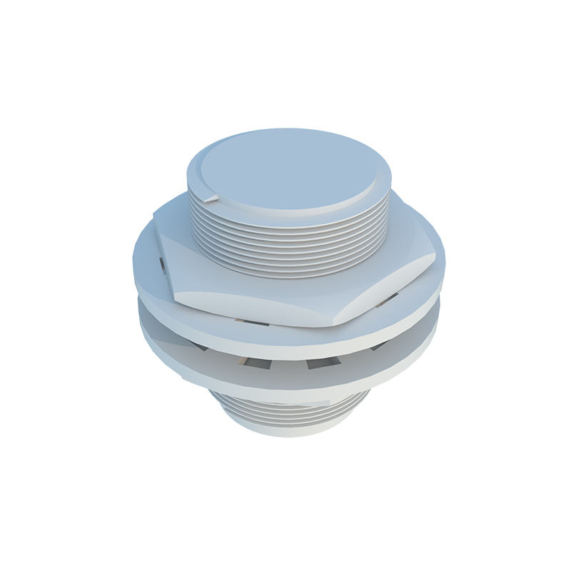
In conclusion, the proximity sensor interface is far more than just wires and connectors. It is a decisive factor in system performance, reliability, and intelligence. From the simplicity of a three-wire DC sink/source output to the advanced bidirectional communication of IO-Link, the interface defines how seamlessly the sensor integrates into the broader control architecture. A deep understanding of these interface options empowers designers to build more responsive, diagnostic-capable, and future-proof automated systems.