In the realm of industrial automation and control systems, proximity switch sensors play a pivotal role in non-contact detection of metallic or non-metallic objects. This article provides a detailed teardown diagram analysis and component breakdown of a typical inductive proximity sensor, offering insights into its internal architecture, operational principles, and key design considerations.
The sensor housing, typically constructed from nickel-plated brass or stainless steel, serves as the primary protective enclosure. Upon removal of the housing, the internal assembly reveals a multi-layered structure. At the core lies the oscillator coil, wound around a ferrite core, which generates a high-frequency electromagnetic field. This coil is connected to an oscillator circuit that sustains oscillations when no target is present. When a metallic object enters the sensing range, eddy currents are induced in the target, causing a change in the oscillation amplitude or frequency. This change is detected by the subsequent evaluation circuit.
Adjacent to the oscillator is the trigger circuit, which processes the signal from the oscillator. It typically comprises a Schmitt trigger or comparator IC that converts the analog oscillation change into a digital output signal. The output stage, often featuring a transistor (NPN or PNP) or a relay, interfaces with the external control system. For DC sensors, the output transistor switches the load, while AC/DC universal types may incorporate a solid-state relay.
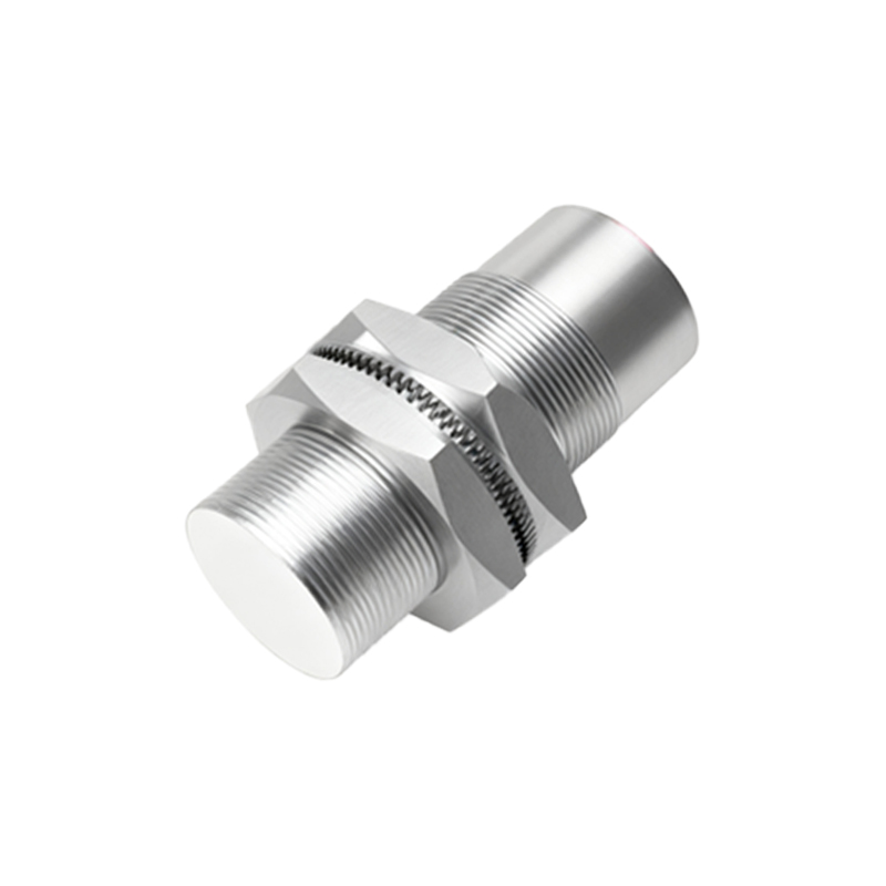
Power supply components include a voltage regulator and filtering capacitors to ensure stable operation amidst industrial electrical noise. The sensor’s sensing face is usually made of a non-metallic material like PBT or ceramic to allow electromagnetic field penetration. Internal potting compound, such as epoxy resin, provides environmental protection against moisture, dust, and mechanical vibration.
Wiring connections are secured via screw terminals or molded connectors, with color-coded leads: brown for DC+, blue for DC-, and black for the output signal. LED indicators for power and output status are often visible through the housing. The teardown diagram highlights the precise arrangement of these components, emphasizing the compact design that maximizes reliability in harsh industrial environments.
Understanding this teardown diagram aids in troubleshooting, such as identifying failed oscillator coils due to overload or damaged output transistors from short circuits. It also underscores design features like short-circuit protection, reverse polarity protection, and temperature compensation circuits that enhance durability. For maintenance engineers, this knowledge facilitates quick diagnostics and part replacement, minimizing downtime.
In summary, the proximity sensor’s internal design reflects a balance of sensitivity, robustness, and efficiency. By dissecting its components through a teardown diagram, professionals gain a deeper appreciation of the engineering principles that ensure precise, non-contact detection in applications ranging from conveyor systems to robotic arms.