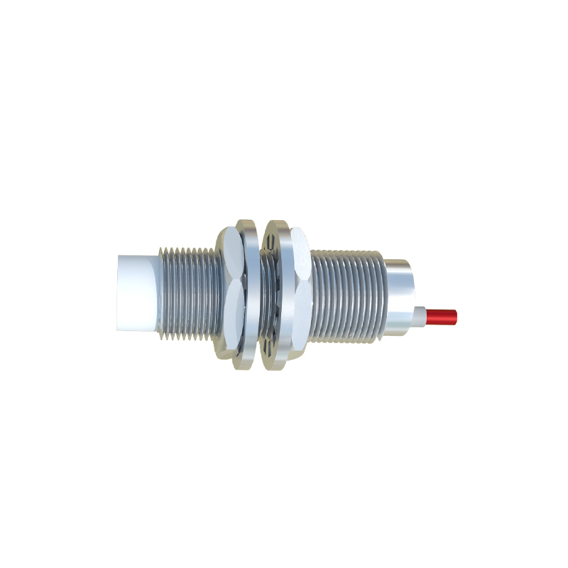
Proximity switch sensors are essential components in modern industrial automation, widely used for position detection, object counting, and safety monitoring. Understanding where to connect these sensors is crucial for ensuring system reliability, operational efficiency, and safety compliance. This article provides a comprehensive guide on proper connection methods, wiring considerations, and practical applications in various industrial settings.
Proximity sensors are typically classified into inductive, capacitive, and photoelectric types, each with specific connection requirements. Most industrial proximity switches operate on DC or AC power supplies, commonly 12-24V DC or 110-230V AC. The connection involves three main terminals: power supply (V+ and V-), output signal (NO/NC), and ground. For DC sensors, the brown wire is usually connected to the positive voltage supply, the blue wire to the negative or ground, and the black wire to the load or controller input. In AC sensors, the brown wire connects to the live terminal, blue to neutral, and black to the output signal.
Proper wiring begins with selecting the correct power source. Ensure the voltage and current ratings match the sensor specifications to prevent damage. Use shielded cables in environments with high electromagnetic interference (EMI) to reduce noise and false triggering. The sensor output can be configured as normally open (NO) or normally closed (NC), depending on the control logic. For instance, in safety circuits, NC configurations are preferred because a broken wire will trigger a fault signal, enhancing system safety.
When connecting to programmable logic controllers (PLCs), proximity sensors are wired to digital input modules. The sensor output acts as a switch, closing or opening the circuit to send a signal to the PLC. For example, in conveyor belt systems, inductive proximity sensors detect metal objects and send signals to the PLC to control motor operations. It is vital to include protective devices such as fuses or surge protectors in the circuit to safeguard against voltage spikes or short circuits.
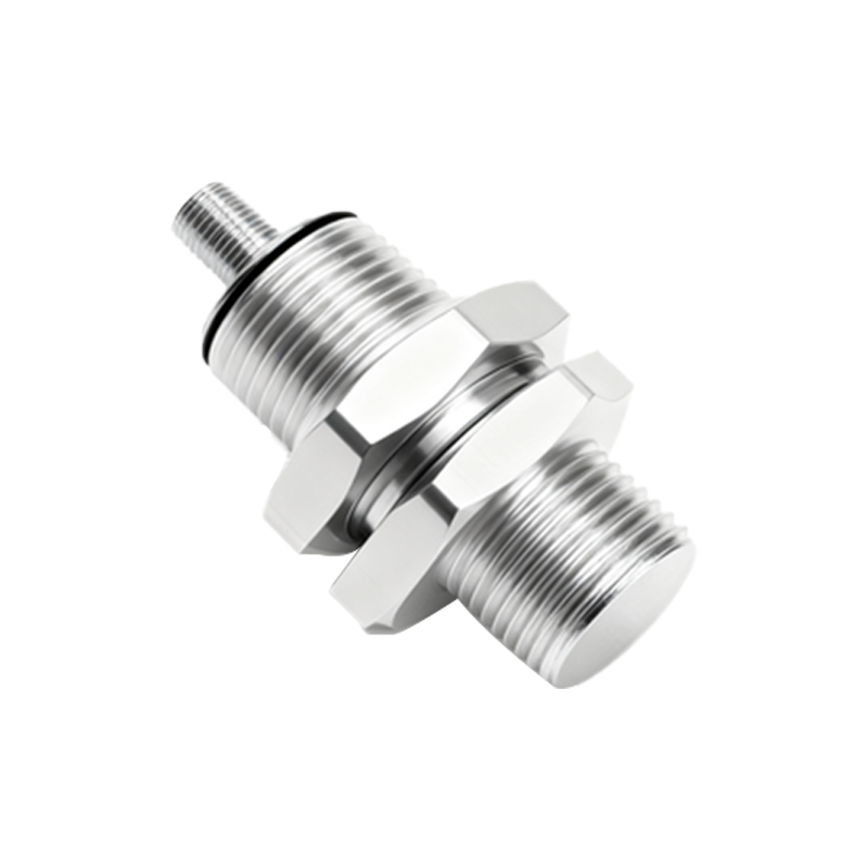
Grounding is another critical aspect. Always connect the sensor’s ground terminal to a common ground point to avoid potential differences that could cause erratic behavior. In multi-sensor installations, use a star grounding configuration to minimize cross-talk and ensure stable operation. Additionally, consider environmental factors like temperature, humidity, and exposure to chemicals, which may require sealed connectors or conduit systems for protection.
Applications vary across industries. In automotive manufacturing, proximity sensors connect to robotic arms for precise part positioning. In packaging machinery, they interface with counters and timers to manage product flow. For hazardous areas, intrinsically safe barriers or isolators are used between sensors and control systems to prevent ignition risks. Regular testing with multimeters or oscilloscopes helps verify connections and diagnose issues like signal drift or intermittent faults.
In summary, connecting proximity switch sensors correctly involves attention to power requirements, output configuration, wiring practices, and environmental adaptations. Following manufacturer guidelines and industry standards such as IEC 60947-5-2 ensures optimal performance and longevity. Proper installation not only enhances automation efficiency but also reduces downtime and maintenance costs, making it a fundamental skill for electrical engineers and technicians in the industrial sector.