Laser sensors are critical components in modern industrial automation, offering precise measurement, detection, and positioning capabilities. As an electrical engineer or technician, understanding how to properly disassemble a laser sensor is essential for maintenance, troubleshooting, or component replacement. This guide provides a detailed, industry-standard procedure to ensure safety and prevent damage to sensitive optical and electronic parts.
Before beginning disassembly, always prioritize safety. Ensure the sensor is completely disconnected from power sources, including any connected controllers or PLCs. Verify that the system is in a lockout/tagout (LOTO) state to prevent accidental energization. Wear appropriate personal protective equipment (PPE), such as safety glasses and anti-static wrist straps, to protect against optical radiation and electrostatic discharge (ESD). Gather necessary tools: precision screwdrivers, hex keys, tweezers, and a clean, static-free work surface.
Start by inspecting the sensor's exterior. Most industrial laser sensors feature a rugged housing, often rated IP67 or higher for dust and water resistance. Identify and remove any mounting brackets or fasteners securing the sensor to machinery. Carefully detach electrical connectors, noting their orientation and pin configurations for reassembly. Use a label maker or tape to mark cables if multiple connections exist.
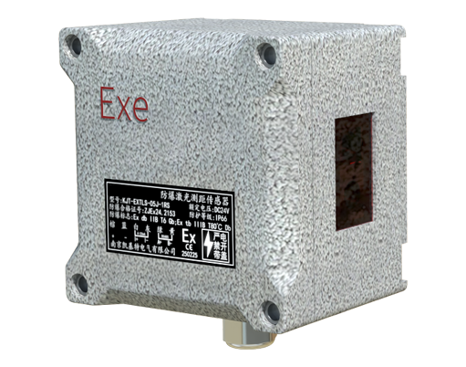
Next, locate and remove the housing screws. These are typically small, precision screws that may require Torx or Allen keys. Keep screws organized in a segmented container to avoid mixing. Gently separate the housing halves. Inside, you will encounter the core assembly: the laser diode module, lens system, photodetector, and signal processing board. Avoid touching optical surfaces directly; use lint-free gloves or optical cleaning tools if handling is necessary.
The laser diode module is often secured by small brackets or adhesive. Document its position relative to the lens and housing. If replacing the diode, desolder its electrical connections carefully, noting polarity. The lens system may consist of collimating or focusing lenses held by retainers. Use tweezers to remove retaining rings, and place lenses on a clean, labeled surface. Clean lenses only with approved optical cleaning solutions and microfiber cloths if contamination is observed.
The photodetector and circuit board are typically mounted together. Disconnect any ribbon cables or pin headers connecting the board to external ports. Remove board mounting screws and lift the assembly out. Inspect for signs of damage, such as burnt components or cracked solder joints. Use an ESD-safe workstation when handling the PCB.

During reassembly, reverse the steps meticulously. Ensure all optical components are aligned according to manufacturer specifications—even minor misalignment can degrade sensor performance. Reattach connectors firmly, and verify housing seals are intact to maintain ingress protection ratings. After reassembly, perform functional tests in a controlled environment before reintegrating the sensor into the system.
Common pitfalls include forcing components, using incorrect tools, or neglecting ESD precautions. Always consult the sensor’s technical manual for model-specific details, as designs vary by manufacturer and application. Regular maintenance, including cleaning and calibration, extends sensor lifespan and ensures reliable operation in demanding industrial settings.