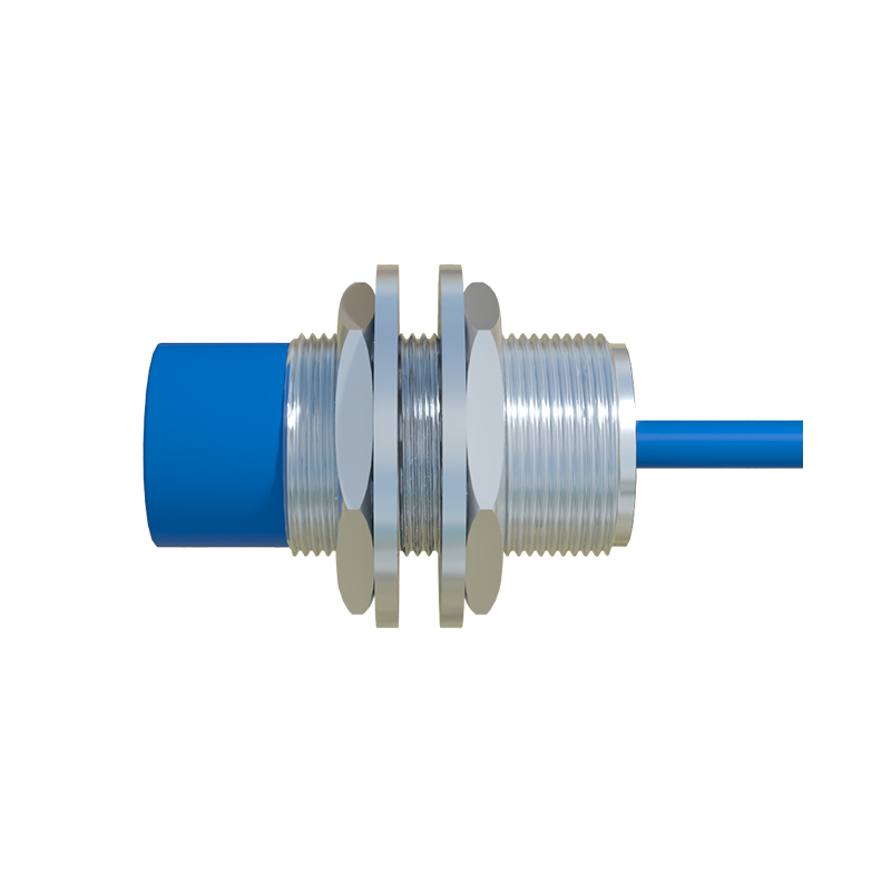
Proximity sensors are essential components in industrial automation, enabling non-contact detection of objects. Proper wiring is critical for reliable operation. This guide provides a clear, step-by-step approach to wiring proximity sensors, based on a detailed video tutorial.
First, identify the sensor type. Inductive proximity sensors detect metallic objects, while capacitive sensors handle non-metallic materials. Check the sensor's datasheet for specifications like operating voltage (commonly 10-30V DC or 90-250V AC) and output type (PNP or NPN for DC, NO or NC for AC). Ensure the power supply matches the sensor's requirements to prevent damage.
For DC sensors, start by connecting the power wires. Typically, brown wire is positive (+), blue wire is negative (-), and black wire is the output signal. Connect the brown wire to the positive terminal of the power supply and the blue wire to the negative terminal. The black wire links to the load (e.g., PLC input or relay). For PNP sensors, the output provides positive voltage when activated; for NNP, it switches the negative side. Always verify connections with a multimeter before powering up.
AC sensors usually have two wires: one for live (brown) and one for neutral (blue). Connect the brown wire to the AC power source's live terminal and the blue wire to neutral. The output is often integrated into these wires, so ensure the load is compatible with AC voltage. Use appropriate insulation and cable glands to protect connections in harsh environments.
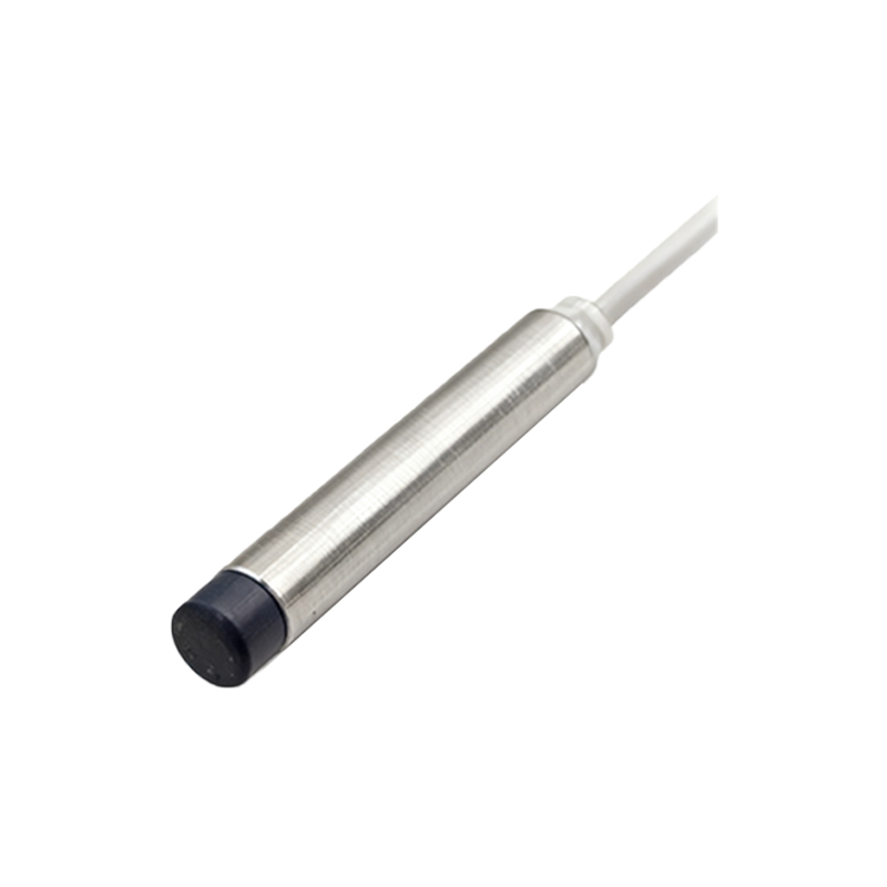
Shielded cables are recommended for long runs or electrically noisy areas to prevent interference. Ground the shield at one end only, typically at the controller side, to avoid ground loops. Maintain proper cable spacing from high-voltage lines to reduce electromagnetic interference.
Testing is crucial. After wiring, power on the system and bring a target object within the sensor's sensing range. Observe the output indicator LED—it should light when the object is detected. Use an oscilloscope or multimeter to confirm the signal voltage matches the datasheet. If the sensor fails to respond, recheck wiring polarity, power supply stability, and sensing distance adjustments.
Common mistakes include incorrect voltage application, reversed polarity for DC sensors, or loose connections. Always follow the manufacturer's wiring diagram, as colors may vary. For complex setups, consult the video guide for visual demonstrations, including troubleshooting tips like checking for short circuits or sensor alignment issues.
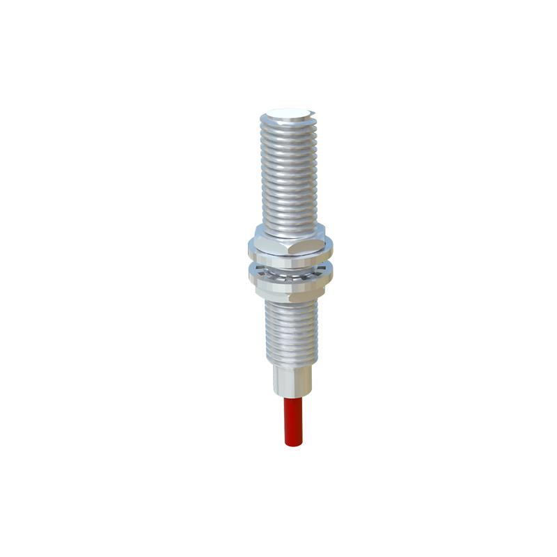
Regular maintenance ensures longevity. Inspect wires for wear, clean the sensor face to prevent false triggers, and verify mounting stability. Proper wiring not only enhances performance but also safeguards equipment and improves safety in automated systems. By mastering these steps, engineers can optimize sensor integration and minimize downtime.