Proximity sensors are critical components in industrial automation, offering non-contact detection of metallic or non-metallic objects. Proper debugging ensures reliable operation and minimizes downtime. This guide provides step-by-step illustrated methods for debugging inductive, capacitive, and ultrasonic proximity sensors commonly used in manufacturing and robotics.
First, verify the sensor's installation. Ensure correct mounting alignment, as misalignment can cause false triggers. The sensing face should be parallel to the target object, with the recommended distance maintained—typically 0.8 to 1.5 times the rated sensing range. Check for obstructions like dust, oil, or debris that might interfere with detection. Use a multimeter to measure voltage at the sensor's output terminal under no-target conditions. For a normally open (NO) sensor, the output should be low (0V for NPN, supply voltage for PNP). When a target enters the range, the output should switch accordingly.
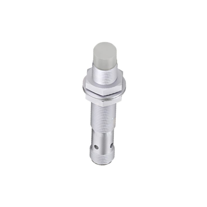
Next, adjust sensitivity settings if available. Many capacitive and ultrasonic sensors feature potentiometers for sensitivity calibration. Turn the potentiometer clockwise to increase sensitivity for detecting smaller or distant objects, but avoid over-sensitivity to prevent interference from background objects. For inductive sensors, ensure the target material matches the sensor's specifications—ferrous metals are detected at longer ranges than non-ferrous ones. If detection is inconsistent, test with a standard target (e.g., a steel plate of specified thickness) to isolate issues.
Wiring and power supply checks are essential. Confirm that the sensor is connected to the correct voltage (e.g., 10-30V DC for most models) and that polarity is observed for DC sensors. Loose connections or voltage drops can cause erratic behavior. Use an oscilloscope to monitor output signals for noise or instability, which may require shielding or filtering. For two-wire AC sensors, verify the load current falls within the sensor's rated range to prevent malfunction.
Environmental factors often impact performance. High temperatures, humidity, or electromagnetic interference (EMI) from nearby motors can affect sensing accuracy. Relocate the sensor or install protective housings if needed. For ultrasonic sensors, air turbulence or temperature variations may alter sound wave propagation—recalibrate in stable conditions.
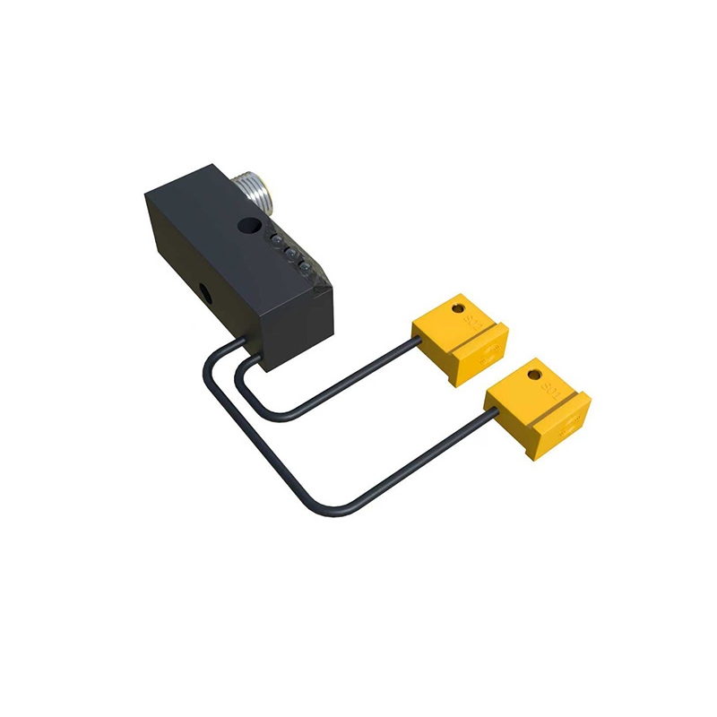
Finally, utilize diagnostic tools like LED indicators. Most sensors have LEDs that show power status and output activation. A steady LED indicates normal operation, while blinking patterns signal faults (e.g., short-circuit or overload). Refer to the manufacturer's manual for specific codes. Document debugging steps and parameters for future maintenance. By following these illustrated methods, engineers can efficiently troubleshoot proximity sensors, ensuring optimal system performance and reducing operational disruptions.