In industrial automation, proximity switch sensors play a critical role in monitoring the position and movement of cylinders, which are fundamental components in pneumatic and hydraulic systems. These sensors detect the presence or absence of a cylinder's piston without physical contact, ensuring precise control and reliable operation in machinery. This article delves into the visual and technical aspects of proximity switch sensors for cylinders, providing insights into their types, installation, and applications through detailed imagery and explanations.
Proximity switch sensors for cylinders are typically categorized into inductive, capacitive, and magnetic types, each suited for specific environments and materials. Inductive sensors, for instance, are ideal for detecting metallic objects like the piston rod or cylinder body, and images often show their compact, cylindrical design with LED indicators for status monitoring. Capacitive sensors can detect non-metallic materials and are useful in applications involving plastic cylinders or liquid levels, with pictures highlighting their adjustable sensing ranges. Magnetic sensors, commonly used with pneumatic cylinders, rely on magnetic fields generated by a piston-integrated magnet, and photographs frequently depict their rugged housing for harsh industrial settings.
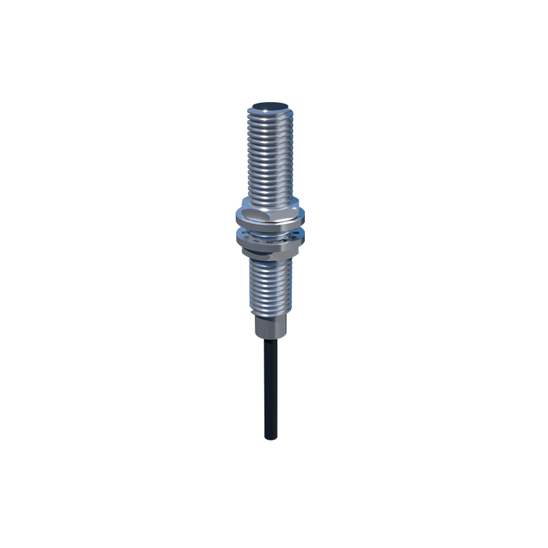
When examining images of these sensors, key features to note include the sensing face, wiring connections, and mounting options. The sensing face is usually the front part that emits the detection field, and it may be shielded or unshielded, affecting the sensor's range and susceptibility to interference. Wiring connections, often shown in close-up shots, involve cables or connectors like M8 or M12 types, which are standard in industrial automation for easy integration. Mounting options vary from threaded barrels for direct installation into cylinder ports to bracket-based systems for external attachment, with images illustrating how proper alignment ensures accurate detection.
Installation and alignment are crucial for optimal performance, as misplacement can lead to false triggers or missed signals. Pictures demonstrating correct installation show sensors positioned parallel to the cylinder's axis, with the sensing face directed toward the target area, such as the piston's end position. In magnetic sensors, images often include diagrams indicating the optimal distance between the sensor and the magnet, typically within a few millimeters, to maintain a strong signal. Additionally, LED indicators visible in photos provide visual feedback on the sensor's operation, with green lights indicating detection and red lights signaling faults or misalignment.
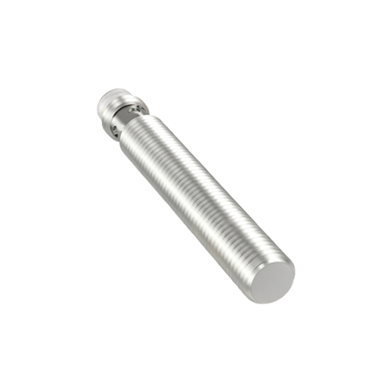
Applications of proximity switch sensors in cylinders span various industries, from automotive manufacturing to packaging lines. In automotive assembly, images might show sensors monitoring cylinder positions in robotic arms, ensuring precise welding or painting operations. In packaging machinery, photographs could depict sensors detecting the extension of cylinders that control conveyor belts, facilitating efficient product handling. These visuals not only aid in understanding the sensor's role but also help engineers select the right model based on environmental factors like temperature, humidity, or exposure to chemicals.
Technical specifications, often highlighted in image captions or accompanying charts, include parameters such as sensing distance, response time, and protection ratings. For example, a typical inductive sensor might have a sensing range of 2-15 mm and a response time of less than 1 millisecond, with an IP67 rating for dust and water resistance. Images of datasheets or labels provide this information, aiding in compatibility checks with cylinder systems. Furthermore, advancements in smart sensors with IO-Link communication are depicted in modern imagery, showing digital interfaces that enable real-time diagnostics and data exchange for predictive maintenance.
In conclusion, proximity switch sensor images for cylinders serve as valuable tools for engineers and technicians, offering visual guidance on selection, installation, and troubleshooting. By analyzing these pictures, professionals can enhance system reliability, reduce downtime, and improve safety in automated processes. As technology evolves, expect to see more high-resolution and interactive images, including 3D models and augmented reality overlays, that further simplify integration and maintenance in the ever-growing field of industrial automation.