In industrial automation and control systems, proximity sensors are indispensable components for non-contact detection of metallic or non-metallic objects. A critical yet often overlooked aspect of their reliable performance is the threaded installation position. This article delves into the engineering considerations, common pitfalls, and best practices for ensuring optimal sensor functionality through correct mechanical mounting.
The primary function of the threaded housing is to provide secure mechanical fixation and precise alignment. Most industrial proximity sensors feature standard metric (e.g., M8, M12, M18, M30) or NPT threads. The installation position directly influences the sensor's sensing range, repeatability, and immunity to environmental interference. For instance, a sensor mounted too deeply within a threaded bore may have a reduced effective sensing distance due to shielding effects from the surrounding metal. Conversely, a sensor protruding excessively might be vulnerable to physical damage or misalignment from mechanical shocks.
A fundamental rule is to respect the specified flush or non-flush mounting characteristics. Flush-mountable sensors can be installed level with a metal surface without performance degradation, whereas non-flush types require a clear frontal area. The installation position must ensure the active sensing face is unobstructed according to its design specification. Engineers must also consider the thread engagement depth. Insufficient engagement risks loosening under vibration, a common issue in machinery. A general guideline is to engage at least 1.5 times the thread diameter into the mounting structure, ensuring the sensor body is seated firmly against a shoulder or using a locking nut as specified.
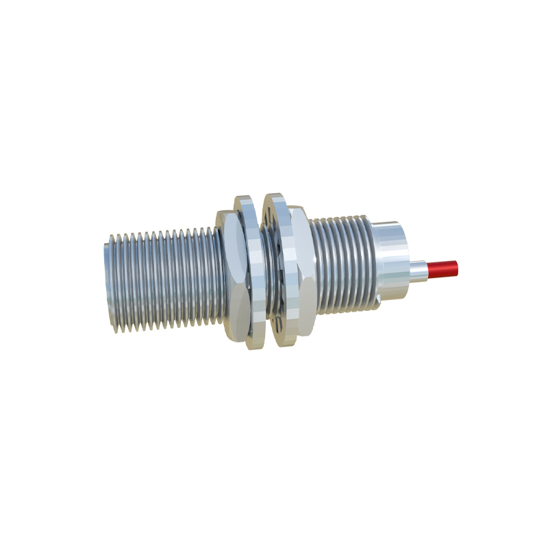
Alignment is another crucial factor. The sensor's central axis should be perpendicular to the target's plane of approach. Angular misalignment can significantly reduce the nominal sensing range. For cylindrical objects, the recommended installation position often involves offsetting the sensor to detect the curved surface optimally. Thermal expansion of mounting materials should also be accounted for in high-temperature environments, as it can alter the relative position over time.
Electrical and environmental sealing is inherently tied to the threaded installation. Proper torque application is vital. Over-tightening can distort the sensor housing, damage internal components, or compromise IP-rated seals (e.g., IP67). Under-tightening may lead to ingress of coolants, oils, or conductive dust. Manufacturers provide specific torque values (e.g., 10-20 Nm for M18 threads) which should be adhered to using calibrated tools. Additionally, the use of appropriate sealing washers or O-rings, and ensuring the mounting surface is clean and flat, prevents leakage paths.
In applications involving multiple sensors, maintaining adequate clearance between adjacent threaded installations prevents mutual interference, especially for inductive sensors generating electromagnetic fields. For sensing non-ferrous metals or under challenging conditions (e.g., heavy washdown), the installation position may need fine-tuning through empirical testing to establish the optimal setpoint.

Ultimately, consulting the manufacturer's datasheet for dimensional drawings, sensing field diagrams, and mounting instructions is non-negotiable. A meticulously planned threaded installation position enhances system reliability, minimizes false triggers, and extends the sensor's operational lifespan, contributing to higher overall equipment effectiveness. By integrating these mechanical considerations into the design phase, engineers can avoid costly retrofits and downtime.