Proximity switch sensors are essential components in modern industrial automation, providing non-contact detection of metallic or non-metallic objects. Proper setup is critical to ensure reliable operation, minimize false triggers, and extend sensor lifespan. This guide outlines key methods for configuring inductive, capacitive, and magnetic proximity sensors in industrial environments.
First, verify the sensor type and specifications. Inductive sensors detect ferrous and non-ferrous metals, typically within a range of 2mm to 40mm. Capacitive sensors can sense materials like plastics, liquids, or powders, with ranges up to 25mm. Magnetic sensors, often used in hydraulic cylinders, respond to magnetic fields. Always consult the datasheet for voltage ratings, output types (PNP/NPN), and environmental limits.
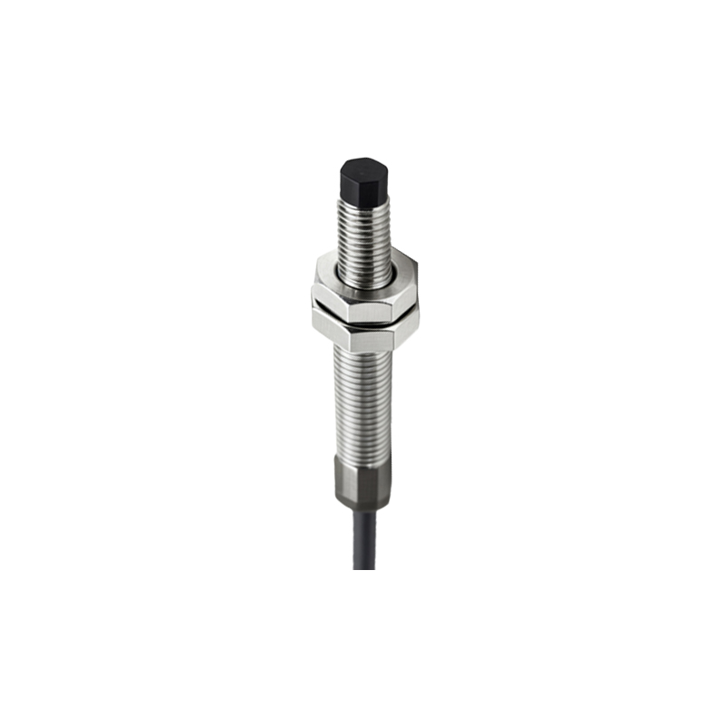
Mounting considerations significantly impact performance. Ensure the sensor is positioned perpendicular to the target object’s approach direction. Maintain the specified sensing distance, accounting for factors like temperature fluctuations or material thickness. For flush-mounted inductive sensors, reduce interference by keeping metallic surroundings at least twice the sensor’s diameter away. Non-flush models require more clearance. Use brackets or adjustable mounts to fine-tune alignment, especially in high-vibration settings.
Wiring must adhere to electrical standards. For DC sensors, connect the brown wire to positive (+V) and the blue wire to negative (0V). The black wire is typically the output signal. For AC models, follow local safety codes. Shield cables in areas with electromagnetic interference (EMI), and avoid running sensor lines parallel to high-voltage cables. Implement surge protection if sensors are near motors or solenoids to prevent voltage spikes.
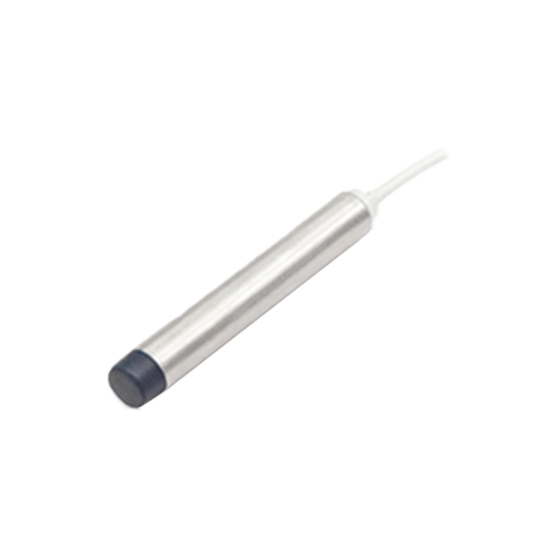
Adjust sensitivity settings where available. Many capacitive sensors feature potentiometers for tuning sensitivity. Start at the lowest setting, then gradually increase until the sensor reliably detects the target without reacting to background objects. For inductive sensors with adjustable hysteresis, set it to prevent oscillation when detecting uneven surfaces. Use teach-in functions on smart sensors to automate calibration for specific materials.
Testing and validation are crucial. Simulate operational conditions by moving the target object at the expected speed and angle. Measure response times to ensure they meet cycle requirements. Check for false triggers caused by nearby machinery, dust, or moisture. In hazardous areas, verify that sensors comply with ATEX or IECEx certifications. Document settings, including sensing distance, delay timers, and output logic, for future maintenance.
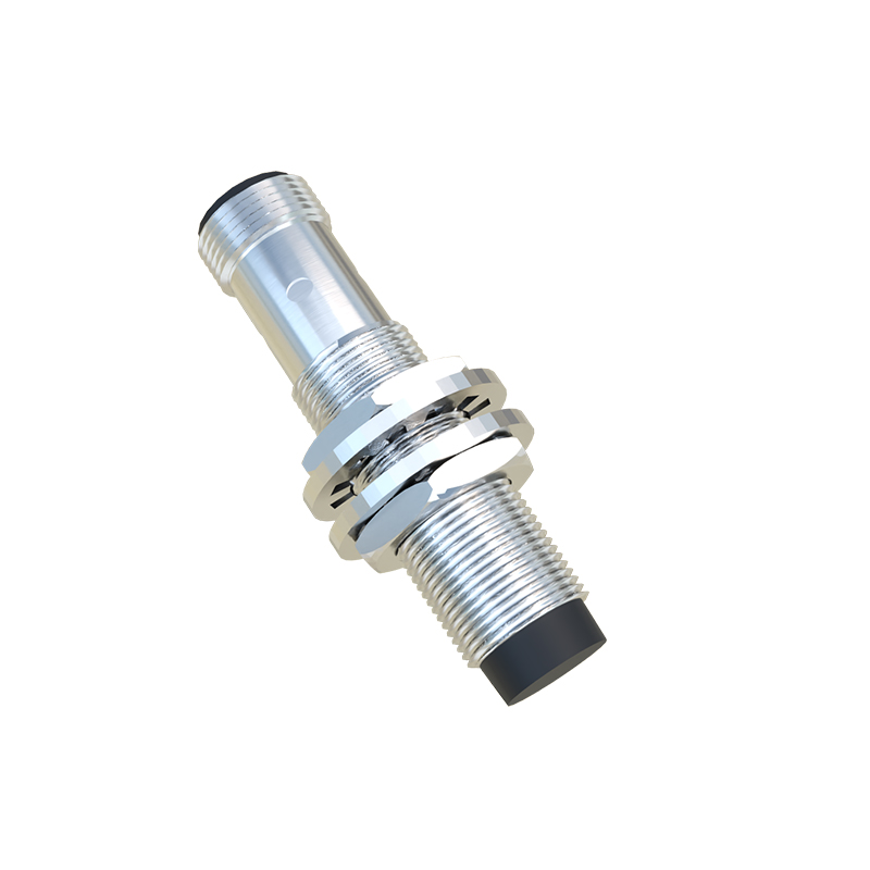
Regular maintenance ensures long-term accuracy. Clean sensing faces to remove oil, debris, or buildup that could reduce range. Inspect housings for cracks or corrosion, especially in washdown environments. Recalibrate sensors annually or after mechanical changes. Monitor output signals with multimeters or PLC diagnostics to detect drift early.
By following these methods, engineers can optimize proximity sensor performance, enhancing system efficiency and reducing downtime. Always prioritize safety by de-energizing equipment during setup and referring to manufacturer guidelines for model-specific nuances.