Proximity sensors are integral components in modern electronics, enabling devices to detect the presence or absence of nearby objects without physical contact. The underlying circuit design is crucial for their accuracy, reliability, and efficiency. This article delves into the fundamental principles and practical implementations of proximity sensor circuits, focusing on common types and their core electronic architectures.
At its heart, a proximity sensor circuit operates by emitting a field or beam of electromagnetic radiation (like infrared light or an electromagnetic field) and then monitoring for changes in the return signal. The primary circuit blocks include an oscillator, a sensing element (emitter and receiver), a signal conditioning unit, and an output stage.
One of the most prevalent types is the Infrared (IR) Proximity Sensor. A basic IR circuit utilizes an IR LED as the emitter and a photodiode or phototransistor as the receiver. The oscillator circuit, often built around a 555 timer IC or a microcontroller, drives the IR LED to emit modulated pulses. This modulation helps the receiver distinguish the emitted signal from ambient IR light. The photodetector's conductivity changes when it receives the reflected IR light. This minute change in current is then fed into a signal conditioning circuit, typically involving an operational amplifier (op-amp) configured as a comparator. The op-amp amplifies the signal and compares it to a preset threshold voltage. When the reflected signal strength exceeds this threshold (indicating an object is close), the comparator's output switches state, triggering the output stage—which could be a simple transistor switch, a relay driver, or a direct logic signal to a microcontroller GPIO pin.
Inductive Proximity Sensors, used for detecting metallic objects, rely on a different principle. Their core circuit centers around a coil that forms part of an LC oscillator. When a metallic object enters the oscillating electromagnetic field, eddy currents are induced in the object, causing a loss of energy in the coil. This results in a change in the oscillation amplitude or frequency. The circuit detects this change, often through an amplitude demodulation stage, and processes it to produce a digital output. These sensors require stable oscillator designs and precise detection circuitry to maintain sensitivity and noise immunity, especially in industrial environments.
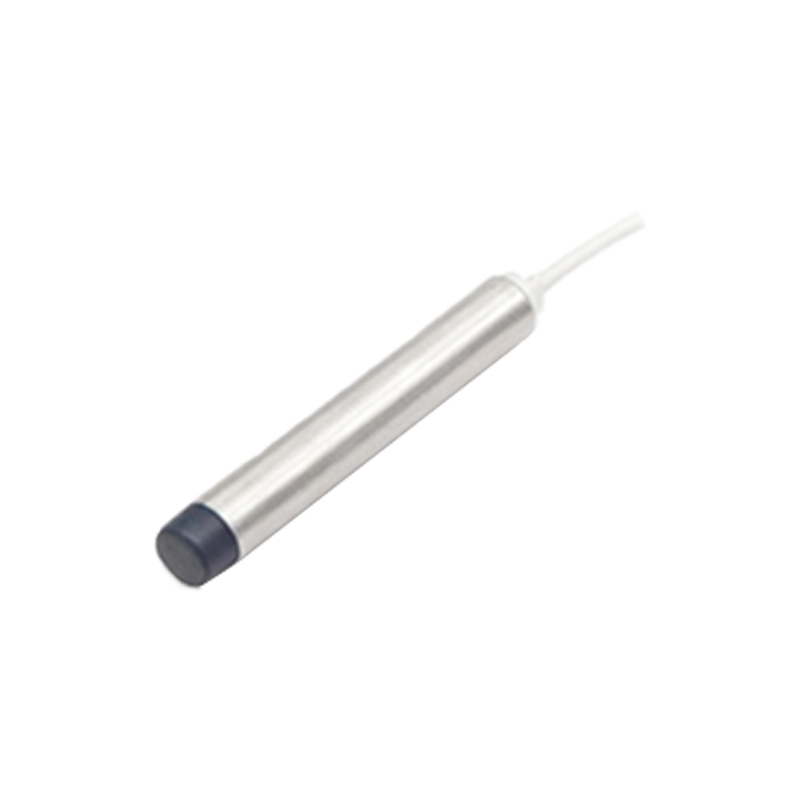
Capacitive Proximity Sensors can detect both metallic and non-metallic objects. Their circuit measures changes in capacitance. The sensor plate forms one plate of a capacitor, with the target object acting as the other plate. The circuit often incorporates the sensor into a relaxation oscillator or an RC timing circuit. As an object approaches, the capacitance increases, altering the oscillation frequency or the charge/discharge time constant. A subsequent monitoring circuit, such as a frequency-to-voltage converter or a microcontroller measuring pulse width, interprets this change to determine proximity.
Key design considerations for all proximity sensor circuits include:
Power Management: Minimizing current draw, especially for battery-operated devices. This involves careful selection of components and using sleep modes for the oscillator and processing circuitry.
Noise Immunity: Shielding the circuit from electromagnetic interference (EMI) and designing filters (like low-pass filters in the signal conditioning path) to reject unwanted signals. Proper grounding and layout are paramount.
Sensitivity and Range Adjustment: Incorporating potentiometers or digital trims (via microcontroller code) to adjust the detection threshold, allowing calibration for different environments and object reflectivities.
Output Interface: Designing a clean, robust output signal. Open-collector NPN or PNP transistor outputs are industry standards for compatibility with Programmable Logic Controllers (PLCs), while direct logic-level outputs suit microcontroller-based systems.
Implementing a functional prototype often starts with a schematic design in an Electronic Design Automation (EDA) tool. Component selection balances cost, size, and performance. For instance, choosing an op-amp with low input offset voltage and high gain-bandwidth product improves sensitivity. Careful Printed Circuit Board (PCB) layout is critical: keeping the oscillator loop small, separating analog and digital grounds, and placing the sensing elements away from noise sources.
Testing and calibration involve verifying the detection range, repeatability, and response time under various conditions (different materials, lighting, temperatures). A systematic approach ensures the final circuit meets the application's specifications, whether for touchless faucets, smartphone screen blanking, robotic obstacle avoidance, or industrial machine safety guards.
In summary, designing a proximity sensor circuit requires a solid understanding of the sensing technology (optical, inductive, capacitive), analog electronic design for signal generation and conditioning, and practical considerations for noise reduction and reliable output. By meticulously integrating these elements, engineers can create effective non-contact detection solutions for a vast array of applications.