Proximity inductive sensors are fundamental components in modern industrial automation, offering non-contact detection of metallic objects. Understanding their schematic is crucial for engineers, technicians, and enthusiasts working with control systems. This article delves into the core principles and typical circuit diagrams that bring these versatile sensors to life.
At its heart, a proximity inductive sensor operates on the principle of electromagnetic induction. The core component is a coil wound around a ferrite core, which forms part of an oscillator circuit. When an alternating current flows through this coil, it generates a high-frequency electromagnetic field at the sensor's active face. This is the "oscillating" state. When a metallic target enters this field, eddy currents are induced on the target's surface. These eddy currents draw energy from the oscillator, causing a reduction in the oscillation amplitude. This energy loss is the key detectable event.
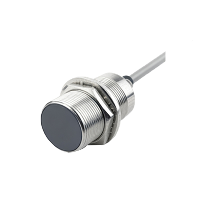
The schematic of a standard three-wire DC sensor, the most common industrial type, reveals the internal architecture. It typically consists of several key stages integrated into a single housing. The first stage is the High-Frequency Oscillator. This circuit, often built around a transistor or an integrated oscillator IC, drives the sensing coil (L1) at a frequency typically between 100 kHz and 1 MHz. Resistors and capacitors set the oscillation frequency and stability. The coil is the central symbol on the schematic, usually depicted next to the sensor face.
The second critical stage is the Demodulator or Amplifier. The signal from the oscillator is fed into this stage. Its job is to convert the change in oscillation amplitude into a smooth DC voltage change. As a metal object approaches, the amplitude drops, and the demodulator outputs a corresponding lower voltage. This stage often includes filtering to ignore slow changes and electrical noise, ensuring only the rapid amplitude shift caused by a target is processed.
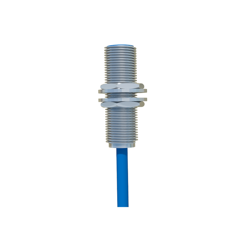
Next is the Trigger/Schmitt Trigger circuit. This component is essential for creating a clean, sharp switching output. The analog signal from the demodulator is compared against a predefined threshold voltage. Once the signal crosses this threshold (indicating a target is within the sensing range), the trigger circuit instantly switches its output state. This hysteresis prevents output chattering if the target is positioned right at the edge of the sensing distance.
Finally, the Output Stage handles the interface with the external control system like a PLC. For an NPN (sinking) output sensor, the schematic shows an NPN transistor with its collector connected to the positive supply (Brown wire), the emitter to the output (Black wire), and a load (e.g., a PLC input) connected between the output and ground (Blue wire). For a PNP (sourcing) output, a PNP transistor is used with the emitter to positive, collector to output, and load to ground. The output stage also includes protection components: a freewheeling diode for inductive loads, and often transient voltage suppression diodes.
A two-wire AC/DC sensor schematic is simpler, where the sensor modulates its internal impedance to switch the current flowing through the single loop. It acts like a variable resistor in series with the load. While simpler externally, its internal schematic still contains a rectifier, regulator, oscillator, and a solid-state switch like a TRIAC for AC models.
When reading a proximity sensor schematic, note the standard symbols: the coil for the oscillator, triangles for amplifiers, the hysteresis symbol for the trigger, and transistor symbols for the output. The power supply connections (V+, 0V) and output signal line are clearly marked. Understanding this flow—from oscillator excitation to amplitude change, signal conditioning, threshold comparison, and final switching—empowers users to troubleshoot effectively, select the right sensor for an application, and integrate it seamlessly into larger control panels. Proper wiring, as per the schematic, is vital to avoid damage from incorrect polarity or overloads, ensuring reliable, long-term operation in demanding industrial environments.