After two decades of wrestling with proximity sensors in steel mills, mining pits, and chemical plants, I can tell you this: the datasheet is a polite fiction. It describes a device operating in a lab-coated world that doesn't exist. Let's cut to the chase with what you won't find in the manual.
Experience Correction: The Gritty Reality of Specs
The advertised sensing range and repeatability are the first casualties in the field. Take a standard 18mm cylindrical inductive sensor rated for 8mm range on mild steel. In a CNC machining cell flooded with conductive aluminum swarf, its effective range can drop to under 4mm. The microscopic particles form a parasitic damping field, absorbing the sensor's electromagnetic energy. I've logged data showing a 35-50% reduction in effective range in dense, conductive debris environments. Similarly, the "10-30V DC" operating voltage range is a trap. On long cable runs (>50m) alongside VFD-driven motors, induced voltage spikes can momentarily push the supply past 30V, not frying the sensor but causing a hard reset and a missed count. The fix isn't a bigger sensor; it's a 5-cent Zener diode and a ferrite clamp at the junction box—a solution born of failure.
Boundary Conditions: When to Walk Away
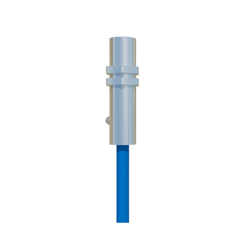
Proximity sensors are not universal detectives. Knowing when not to use them is more critical than installation. Here are the failure zones:
1. Non-Homogeneous Targets: Detecting the level of powdered cement or granular plastic in a silo? Forget standard capacitive sensors. The material's dielectric constant varies wildly with compaction, moisture (even 2% variance), and static charge, leading to ±30% level detection errors. It's a guessing game.
2. High-Speed, Low-Mass Targets: A photoelectric or ultrasonic sensor is superior for detecting lightweight plastic caps on a conveyor at 5m/s. An inductive sensor's eddy current effect requires sufficient mass for a clean signal; a 2-gram cap may not trigger it reliably, causing intermittent faults that defy diagnosis.
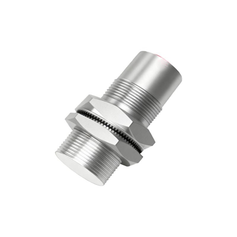
3. Extreme Thermal Gradients: Mounting a sensor on a hydraulic press cylinder seems logical. However, the thermal expansion of the cylinder housing (e.g., from 20°C to 120°C) can shift the mounting position by over 0.5mm—enough to push a precisely gapped sensor out of its hysteresis window, causing failure at the worst moment. The sensor works; its mechanical context doesn't.
Counterintuitive Conclusion: Sometimes, Less Sensing is More
The most reliable system I designed used a reduced sensing range. We were detecting stainless steel pistons in a high-pressure water jet system (ambient: constant mist). Standard waterproof (IP67) inductive sensors failed within weeks. Corrosion? No. The high-pressure micro-droplets, traveling at high speed, created a thin, continuous film on the sensor face. This film, while thin, had enough capacitance to slightly alter the oscillator's baseline, causing false triggers. The solution was counterintuitive: we selected sensors with a shorter nominal range (5mm instead of 10mm) and under-ran them at 60% of their rated capacity (2mm gap). This provided a stronger, more focused field less susceptible to surface film capacitance noise. Reliability increased from 200 hours to over 10,000 hours MTBF. The lesson: chasing maximum range often minimizes stability. Derating, in this context, is not a compromise but a precision strategy.
The goal isn't to memorize specs but to understand the physics of failure. Your most powerful tool is a logbook of what broke and why, written in the language of reality, not theory.