For two decades, I've specified, installed, and cursed laser sensors in environments that would make a lab technician weep. Forget the pristine graphs and theoretical specs. Real-world performance is a negotiation between physics and harsh reality. Here’s what the brochures and application notes won’t tell you.
Experience Corrections: Where Theory Meets the Grime
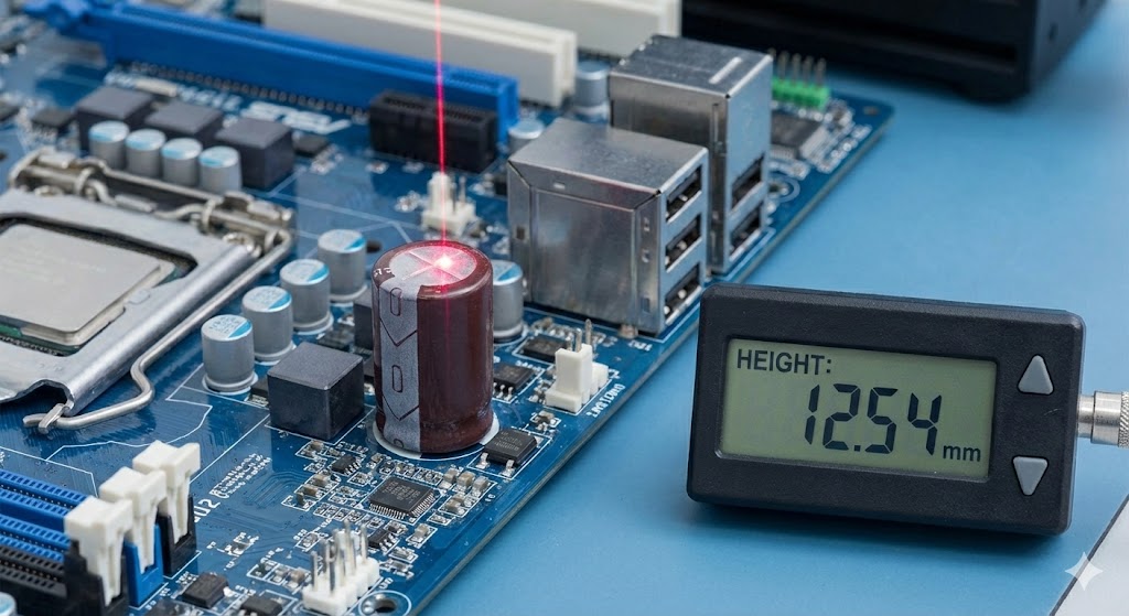
The advertised 0.1% linearity and sub-millisecond response are seductive. In practice, they are conditional privileges, easily revoked. Take the critical parameter of measurement stability. Datasheets quote figures for a controlled 20°C ambient. On a factory floor near an injection molding machine, ambient swings of 15°C are common. The resulting thermal drift in the sensor's internal optics and electronics can introduce a systematic error of 0.5-1% of full scale, completely overshadowing the pristine repeatability spec. You haven't calibrated your sensor until you've characterized its performance across your *actual* temperature envelope.
Then there's the matter of surface dependency. The "ideal diffuse reflector" is a myth. Most sensors are calibrated on a standard white ceramic tile. Shiny aluminum, dark rubber, or wet surfaces will skew the triangulation or time-of-flight calculation. I've seen measurements on oxidized steel deviate by +2% and on glossy black plastic by -3% compared to the calibration target. The fix isn't a better sensor; it's a rigorous, on-material calibration during commissioning, creating a bespoke offset table for each target type in your process.
Boundary Conditions: When to Walk Away
Laser sensors are not universal solutions. Deploying them outside their physical boundaries is an expensive lesson in failure.
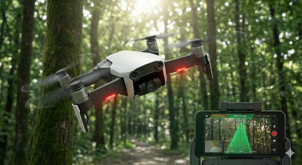
First, forget about reliable operation in environments with heavy airborne particulates: fine powder, steam, oil mist, or dense smoke. A 650nm laser beam scattering through powder coating overspray isn't just attenuated; the backscattered light creates signal noise that the receiver interprets as a false, closer object. The result is erratic, unusable data. In such conditions, a contact probe or a radically different technology (e.g., ultrasonic with advanced filtering) is the only sane choice.

Second, high-vibration environments are a silent killer. A sensor rated for 10g vibration might survive mechanically, but its measurement integrity won't. Vibrations at specific frequencies can induce micro-movements in the laser diode mount or receiver lens, manifesting as high-frequency noise (jitter) on the output signal. This isn't filtered by standard algorithms. I diagnosed a chronic ±0.2mm jitter on a robotic welding cell not to electrical noise, but to a resonant vibration at 87Hz from the robot's servo motors. The solution was a custom isolation mount, not a new sensor.
Third, avoid using standard sensors for rapid measurements on highly transparent or translucent materials (clear glass, thin films). A significant portion of the laser passes through, and the reflected signal from the intended surface is weak and mixed with reflections from secondary surfaces. The sensor either fails to lock or picks an arbitrary reflection plane. For these applications, you need a sensor with a specifically tuned wavelength and receiver optics designed for low-reflectivity targets—a niche and costly variant.
Counter-Intuitive Conclusions: Data-Driven Heresies
1. Sometimes, a Lower Resolution Sensor is More Accurate. In high-speed dynamic tracking (e.g., measuring tire runout at 2000 RPM), a sensor with a 10µm resolution and a 50kHz sampling rate will drown you in noise. A sensor with a "coarser" 50µm resolution but superior signal processing and a 5kHz bandwidth will deliver a cleaner, more stable, and ultimately more *truthful* analog output. Precision is not accuracy. Chasing the former often sacrifices the latter in real-time control loops.
2. The "Sealed" IP67 Housing is a Liability in Washdown. This is critical: an IP67 (submersible) rating means it survives a temporary dunk. It does *not* mean it can withstand daily high-pressure, high-temperature chemical washdowns. The repeated thermal cycling and pressure differentials will eventually breach the static O-ring seals. Condensation forms inside the lens. I have a graveyard of IP67 sensors that died this way. For harsh washdown (FDA, dairy, pharma), you must insist on a sensor with a *pressurized purge port* or one specifically rated for hygienic design (e.g., EHEDG, 3-A). The standard industrial "sealed" unit is a ticking time bomb.
3. Analog Output is Often More Robust Than Digital. In the age of IO-Link and Ethernet, this sounds archaic. However, in electrically noisy environments (arc welders, large motor drives), a 4-20mA analog signal, properly shielded and grounded, is inherently immune to the digital corruption that can plague serial communication packets. A corrupted digital packet is a lost measurement. A noisy analog signal can often be filtered effectively at the PLC. For mission-critical measurements where a single missed data point halts a line, the simplicity and deterministic nature of analog can be the safer, more reliable choice. Don't digitize just because you can.
The ultimate metric is not sensor specifications, but the reduction in process variation and mean time between failures in *your* application. Choose accordingly.