Forget the pristine datasheets and lab-perfect application notes. After twenty years of deploying inductive proximity sensors in steel mills, chemical plants, and automated foundries, I’m here to talk about what happens when theory meets a grinder full of metal shavings and a washdown hose. The real value isn't in knowing they detect metal; it's in knowing precisely when and why they won't.
Experience Correction: The Myth of the Nominal Sensing Distance (Sn).
The published Sn is a fantasy under industrial duress. The primary deviation isn't temperature or voltage—it's target material and surface condition. While the correction factor (K) for mild steel is 1.0, for stainless steel (austenitic, e.g., 304) it drops to ~0.7-0.75 in theory. In practice, on a hot, work-hardened stainless conveyor part, I've measured effective factors as low as 0.6. The更大的偏差 comes with non-ferrous metals. For brass, the textbook says ~0.4-0.5. But if that brass is a cast, porous component with high lead content, expect 0.3-0.35. The sensor doesn't see "brass"; it sees electrical conductivity and magnetic permeability. Anodized aluminum? The oxide layer is an insulator. I've seen installations fail because the 2-mil anodized coating pushed a sensor with a nominal 8mm range below its reliable detection threshold for the bare aluminum spec. The fix was always to derate the effective Sn by at least 40% for any non-standard target and verify on the actual, dirty, often oxidized part.
Boundary Conditions: Where These Sensors Become Liabilities.
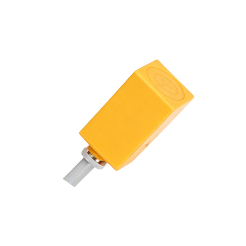
Inductive sensors are not universal metal detectors. Their failure zones are specific and dangerous.
1. Fine, Conductive Particulate Environments: This is the killer. In machining centers processing graphite or carbon-fiber composites, or in facilities with pervasive aluminum or brass dust, the sensor face will gradually become coated. This coating forms a conductive "shield." The oscillator's field is absorbed by this layer, dramatically reducing the effective range, often causing intermittent failure long before total shutdown. In one case, a sensor checking a robotic gripper for a brass part failed every 72 hours on average due to dust accumulation. The solution was not a "more robust" sensor, but a complete shift to a pneumatic contact solution.
2. Extreme Electromagnetic Noise Sources: While most are rated for welding environments, the boundary is di/dt—the rate of current change. Resistance spot welders are usually fine. However, near large induction heating coils or the arc initiation of a plasma cutter, the transient magnetic fields can be so intense they saturate the sensor's core or induce false signals in the output circuitry. I documented a case where sensors within 1.5 meters of a 25kHz induction heater would latch on and require a power cycle. The boundary is not distance; it's the rate of change of the external field. If you can hear arc noise on an AM radio, your inductive sensor is in jeopardy.
3. Flowing Media with High Metallic Content: Using an inductive sensor to detect the level of a liquid, even a conductive one like coolant, is fraught. The boundary condition is turbulence and air bubbles. A stable, homogeneous fluid might work. But in a sump with swirling chips and tramp oil, the changing density and air gaps create a wildly fluctuating signal, making reliable point-level detection impossible. It's the wrong tool for the job.
Counter-Intuitive Conclusion: A "Faster" Sensor Can Make Your Machine Slower.
Manufacturers tout response times in microseconds. The instinct is to choose the fastest sensor for high-speed indexing. This is often wrong. In high-vibration environments (e.g., stamping presses, riveting machines), an ultra-fast sensor can resolve the mechanical vibration as a series of discrete pulses. I've seen a 0.1ms response time sensor on a vibrating bowl feeder produce a chattering output that confused the PLC, causing random stops. The slower, "inferior" 3ms sensor acted as a natural filter, providing a clean, stable signal. The machine's overall cycle time improved because it stopped faulting. The insight: Match the sensor's temporal resolution to the mechanical reality, not just the electronic ideal. Sometimes, you need a sensor that's deliberately "dumb" and slow.
The final truth is this: The reliability of an inductive proximity system is determined 90% by the rigor of the failure mode analysis during design and 10% by the component selected. Specifying one without a brutal, honest assessment of the real-world boundary