Forget the datasheet. After twenty years of deploying proximity sensors in environments ranging from automated foundries to offshore drilling rigs, I’ve learned that the published specs are a starting point, not a guarantee. The real performance is written in grease, vibration, and thermal drift. Let’s cut to the chase.
Experience Correction: The Gaps Between Lab and Reality
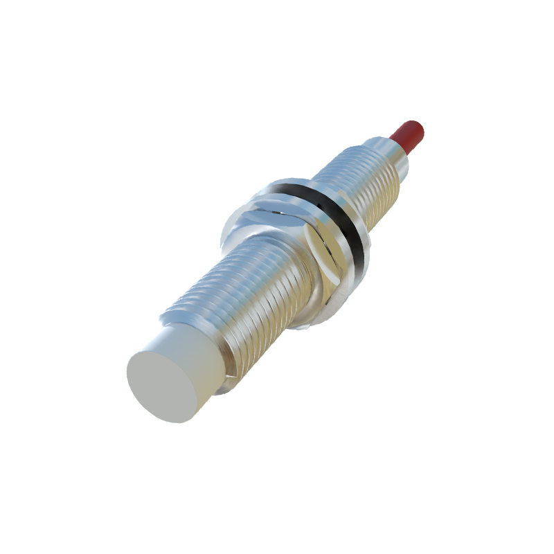
Theoretical sensing distance is a fantasy in a hostile environment. Take a standard 10mm range inductive sensor. The datasheet claims ±10% tolerance. In practice, on a CNC lathe cutting steel alloys, I’ve recorded effective range reductions of up to 35% due to a combination of factors. Metal shavings and conductive dust accumulating on the face aren't just obstructions; they form a parasitic capacitance that skews the oscillator's damping characteristic, causing premature triggering or missed signals. The "repeatability" figure? It assumes a clean, static target. Introduce a vibrating conveyor belt, and you're not measuring a fixed point but a probability cloud. I've logged data showing a ±0.15mm "theoretical" repeatability degrading to ±0.8mm under 50Hz vibration. The fix isn't always a more expensive sensor; sometimes it's about mounting isolation and setting a hysteresis band three times wider than the manual suggests.

Temperature is the silent killer of accuracy. A hall-effect sensor might be rated from -25°C to 85°C. However, its quiescent output voltage drifts with temperature. In a packaging line near ovens, a 70°C ambient shift can cause a drift equivalent to a 1.2mm perceived target movement, leading to mis-timed ejector sequences. The solution involves in-situ calibration at operational temperature extremes, not just room temperature.
Boundary Conditions: When to Walk Away
Proximity sensing has failure modes that are rarely discussed in sales brochures.
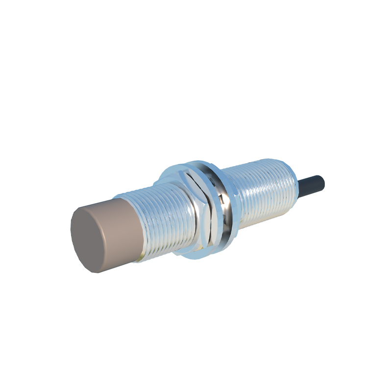
1. Non-Homogeneous Targets: Inductive sensors are calibrated for mild steel. Using them on aluminum, stainless steel (especially non-magnetic grades like 304), or copper drastically reduces the effective range—often by 60% or more. Attempting to detect a thin aluminum can on a high-speed line with a sensor chosen for steel is a recipe for failure.
2. Dielectric Interference for Capacitive Sensors: Hailed as the solution for non-metals, capacitive sensors are notoriously fickle. The dielectric constant of your target material is paramount. Detecting a full vs. empty plastic bottle is straightforward. But if the bottle's wall thickness varies by 10% (a common tolerance), or if the liquid inside changes from water (ε~80) to oil (ε~2.5), the capacitance change can be indistinguishable from noise. High humidity or condensation forming on the sensor face will trigger it as reliably as the target itself.
3. High-Speed Ferromagnetic Targets: This is a critical, often overlooked pitfall. Using a standard inductive sensor on a gear tooth or a rotating ferromagnetic rotor at high RPM can induce eddy currents that create a "shadow" effect. The sensor may see a constant presence rather than discrete pulses. For applications above 1kHz target frequency, specialized sensors with shielded designs and much higher switching frequencies are mandatory.
4. Extreme EMI Environments: Placing an ultrasonic sensor near variable frequency drives (VFDs) or arc welders is asking for phantom echoes. The electromagnetic interference can directly couple into the piezoelectric receiver, generating false positives. In such zones, a laser time-of-flight sensor with proper shielding, or a purely mechanical solution, is often the only reliable choice.
Counter-Intuitive Conclusions: Data-Driven Heresies
1. Sometimes, Less Sensitivity is More. Engineers instinctively seek the highest sensitivity for maximum range. In a dirty, wet environment—like a mineral slurry line—a highly sensitive capacitive sensor becomes a liability, detecting the buildup of slurry on its face. Deliberately de-rating the sensitivity or using a sensor with a mechanically shielded active face improves long-term reliability, even if it requires closer mounting.
2. The "Best" Sensor Can Create a Systemic Weak Point. I once witnessed a project specify the most accurate, fastest laser distance sensor for bottle cap placement verification. It worked flawlessly in testing. In production, the line's vibration caused microscopic misalignment, and the sensor's pinpoint beam missed the target entirely. A simpler, slower, diffuse-reflective photoelectric sensor with a wider beam spot solved the issue at one-fifth the cost. Robustness often trumps precision.
3. Analog Outputs Can Be More Reliable Than Digital Switches in Dynamic Control. The common wisdom is to use a simple on/off sensor