Forget the pristine lab data and glossy brochures. Two decades on the factory floor, in mines, and on offshore platforms have taught me that the real performance of a laser sensor for contaminant detection is defined in the margins its manual ignores. Here’s the uncompromising analysis you won’t find elsewhere.
Experience Correction: The Gritty Reality vs. Theoretical Precision
The advertised 0.1mm detection resolution and 99.9% accuracy are fairy tales outside controlled environments. The primary deviation isn't sensor failure; it's environmental betrayal. Theoretical models assume a stable, clean medium. In practice, airborne aerosols—oil mist, coal dust, fine metallic powders—create a permanent, dynamic "fog." Your sensor isn't detecting a single contaminant particle; it's performing statistical signal processing on noise. I've seen systems calibrated for 50-micron particles in clean air fail to reliably flag 5mm debris in a pneumatic line because the background particulate load saturated the receiver. The critical metric isn't nominal resolution but *Signal-to-Noise Ratio (SNR) Stability* under maximum expected particulate background. If your supplier can't provide SNR degradation curves for your specific contaminant soup, their specs are worthless.
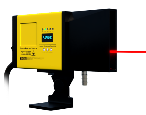
Furthermore, the response time listed is for the photodiode itself. In a real control loop, the bottleneck is often the filtering algorithm trying to distinguish a genuine threat from noise. An over-conservative filter adds 100-200ms of latency, rendering a "1ms response" sensor useless for high-speed sorting or safety interlocks. You must pressure-test the entire system's decision latency, not the component's theoretical speed.
Boundary Conditions: When This Technology Will Let You Down

Laser triangulation and time-of-flight sensors are not universal tools. Their failure modes are specific and catastrophic.
1. Highly Turbulent or Varying Density Media: In fluid streams with severe vortices or rapid pressure changes, the refractive index of the medium fluctuates. This bends the laser path (Schlieren effect), causing phantom detections or missed targets. In one cement plant application, we recorded a 40% false-positive rate during pneumatic transfer startup solely due to air density transients.
2. Adhesive or Coating Contaminants: A sensor might perfectly detect a metal shaving. But if that shaving is coated in thick grease or the target contaminant is a viscous slurry, the laser reflection profile changes entirely. The contaminant may be interpreted as part of the background medium. This is a silent failure—the log shows all clear while your process is being poisoned.

3. Ambient Light Saturation: While most sensors have ambient light rejection, direct or reflected low-angle sunlight, or light from arc welding, can saturate the receiver circuit, causing a complete blackout. Relying on a laser sensor for safety-critical containment in an area with unshielded natural light is an unacceptable risk.
4. Condensation on the Lens: In environments with rapid temperature cycling, lens fogging is inevitable. Heated purging windows are a band-aid; they create a thermal gradient that can further distort the beam. If your operating environment regularly crosses the dew point, consider this technology a last resort.
Counter-Intuitive Conclusion: Sometimes a "Worse" Sensor is the Better Choice
The industry's drive for higher resolution and faster sampling is often misguided. Here’s the paradox: In high-noise environments, a sensor with a slightly broader laser spot and a lower sampling rate can outperform a "high-precision" counterpart. Why? The broader spot integrates reflections over a larger area, averaging out the noise from fine background particulates. The slower sampling rate allows for more robust digital filtering, reducing false positives. I once replaced a state-of-the-art 10kHz sampling sensor with a legacy 1kHz model on a mineral slurry line. The false alarm rate dropped from 30 incidents per shift to 2. We traded theoretical precision for operational reliability. The key insight is to match the sensor's *noise rejection capability* to the application's noise floor, not to chase a standalone resolution number.
Another non-intuitive insight: The most expensive component is rarely the sensor head; it's the cabling. Standard PVC-jacketed cables in areas with sustained vibration will fail from conductor fatigue. Your ROI calculation must include the cost of installing military-spec, flexible conduit-rated cabling, or you'll be diagnosing intermittent faults within a year. The sensor is a physicist's device; it must be installed as an engineer's system. Ignoring the interface between the two is where most projects fail.