Proximity sensors are fundamental components in modern automation, robotics, and safety systems. Their ability to detect the presence or absence of an object without physical contact is largely enabled by a core electronic building block: the oscillator circuit. This analysis delves into the operational principles, common topologies, and critical performance parameters of oscillator circuits used in inductive and capacitive proximity sensors.
At its heart, a proximity sensor oscillator generates a continuous, high-frequency alternating signal. In an inductive sensor, this signal drives a coil, creating an oscillating electromagnetic field. When a metallic target enters this field, eddy currents are induced within the target. These currents draw energy from the oscillator coil, effectively increasing the losses in the resonant circuit. This energy loss manifests as a change in the oscillator's amplitude or, in some designs, its frequency. A subsequent detection circuit monitors this change and triggers the sensor's output switch.
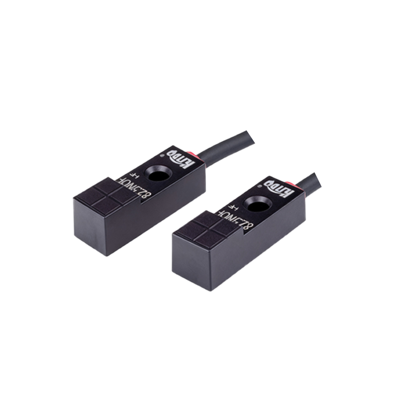
Capacitive sensors operate on a similar oscillatory principle but respond to changes in capacitance. The sensor's active face and the target form two plates of a capacitor. As a target approaches, the capacitance increases. This capacitance is part of the oscillator's resonant tank circuit. An increase in capacitance changes the resonant frequency of the oscillator. The circuit is typically designed to stop oscillating or shift its frequency dramatically when the capacitance reaches a threshold set by the sensing distance, which is then detected.
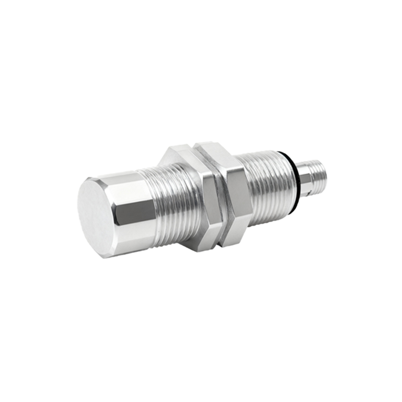
Two prevalent oscillator circuit topologies are employed: the Colpitts and the Hartley oscillators. The Colpitts oscillator, known for its reliable performance and simple design using a split capacitor feedback network, is extremely common in proximity sensor applications. Its frequency stability is adequate for the purpose, and it provides a clear amplitude change in response to target interaction. The Hartley oscillator, utilizing a tapped inductor, is also used, particularly where specific coil characteristics are advantageous. More advanced designs may incorporate crystal or ceramic resonators for exceptional frequency stability in specialized applications.
Key to the sensor's performance is the concept of the "critical damping point." The oscillator is designed to operate in a marginally stable state. The feedback and gain are carefully calibrated so that the introduction of a small additional loss (from a metal target) or a small increase in capacitance is sufficient to push the circuit into a non-oscillating condition. This sharp transition ensures a clean, definitive switching action with minimal hysteresis. Factors such as the Q-factor (quality factor) of the resonant LC tank circuit are crucial. A high Q-factor means a sharper resonance peak, making the oscillator more sensitive to small changes in loss or capacitance, but potentially more susceptible to drift from temperature or component variations. Designers must balance sensitivity with stability.
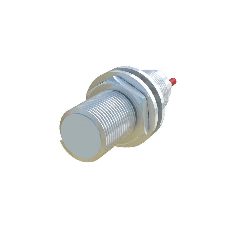
The choice of operating frequency is a critical design decision. Typical frequencies for inductive sensors range from 100 kHz to over 1 MHz. Lower frequencies offer greater sensing ranges for ferrous metals but are less sensitive to non-ferrous metals like aluminum or copper. Higher frequencies improve sensitivity to non-ferrous metals and allow for smaller coil sizes, enabling more compact sensor designs, but may have reduced overall range. The frequency also influences the sensor's immunity to electromagnetic interference (EMI) and its potential to interfere with other equipment.
Analysis of the circuit also involves the output stage. The high-frequency AC signal from the oscillator is rectified and smoothed to produce a DC voltage level. This DC level is proportional to the amplitude of oscillation. A comparator circuit continuously monitors this DC level against a precise reference voltage. When the target-induced damping causes the amplitude to fall below the threshold, the comparator's output state changes, activating the sensor's solid-state switch (PNP, NPN, or analog output). Modern integrated circuits combine the oscillator, amplifier, detector, and output driver into a single package, greatly simplifying design and improving reliability.
In conclusion, the oscillator circuit is the active sensing element of a proximity sensor. Its design—from topology and component selection to frequency and Q-factor—directly determines the sensor's range, sensitivity, target material compatibility, and stability. A thorough analysis of this circuit provides essential insight into the capabilities and limitations of the sensor, guiding proper selection and application in complex industrial systems.