In the vast landscape of industrial automation, the reliable detection of object presence, position, and speed is paramount. Among the diverse array of sensing technologies, turbine type proximity sensors stand out for their unique operational principle and robust performance in specific demanding environments. Unlike common inductive or capacitive sensors, these devices utilize a mechanical-to-electrical conversion method that offers distinct advantages, particularly in applications involving rotating machinery.
The core operating principle of a turbine type proximity sensor is elegantly straightforward. The sensor itself is typically mounted in close proximity to a rotating shaft or component. Attached to this shaft is a small turbine or impeller, often made of metal or a durable polymer. As the shaft rotates, the turbine's blades pass by the sensor head. The sensor contains a permanent magnet and a coiled conductor. Each time a turbine blade passes through the magnetic field generated by the magnet, it causes a disturbance or change in the field. This change induces a small, pulsed electrical current in the coil. The frequency of these electrical pulses is directly proportional to the rotational speed of the shaft. Therefore, the sensor does not measure proximity in the traditional sense of distance to a single object, but rather the proximity of the rotating blades to the sensing element, translating rotational motion into a usable electrical signal.
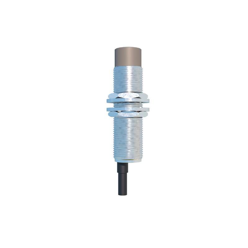
This fundamental principle grants turbine sensors several key characteristics. First and foremost is exceptional reliability in harsh conditions. Having no direct electrical contacts or sensitive optical components, they are inherently resistant to contaminants such as oil, grease, dust, and moisture. This makes them ideal for use in heavy industrial settings like manufacturing plants, automotive assembly lines, and pulp and paper mills. Their output is a consistent AC voltage signal whose frequency varies with speed, providing a simple and noise-resistant signal for monitoring purposes.
The primary application of turbine type proximity sensors is rotational speed monitoring and detection. They are extensively used as tachometers on motors, engines, conveyors, and fans. By monitoring pulse frequency, systems can determine if a machine is running, confirm its operational speed, and trigger alarms or shutdowns if the speed deviates from a set range, indicating potential failure or overload. Another critical application is in safety interlocking systems. For instance, on a guarded machine, a sensor monitoring the spindle can ensure the tool has completely stopped rotating before a safety door is allowed to open. They are also employed in flow sensing, where a turbine placed in a fluid stream rotates at a speed proportional to flow rate, with the proximity sensor picking up the blade pulses.
Selecting the right turbine type proximity sensor requires careful consideration of several parameters. The operating speed range is crucial; the sensor must be capable of generating a clear signal at both the minimum and maximum expected rotational speeds. The material and number of blades on the turbine affect signal strength and resolution. Environmental factors like ambient temperature, potential chemical exposure, and levels of vibration must align with the sensor's ingress protection (IP) rating and construction materials. Output signal type is another decision point; while a raw AC signal is common, some integrated models include signal conditioning electronics to provide a clean square wave or even a 4-20 mA analog output proportional to speed.
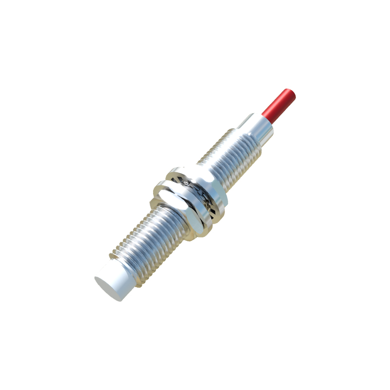
Installation and maintenance are relatively simple but demand precision. The air gap between the turbine blade tips and the sensor face is critical and must be set according to manufacturer specifications—typically a small distance of a few millimeters. An incorrect gap can lead to weak or no signal. Regular maintenance involves checking this gap and ensuring the turbine blades are clean, undamaged, and free from debris buildup that could imbalance the rotor or impede rotation.
While newer technologies like Hall effect sensors or laser tachometers offer high precision, the turbine type proximity sensor remains a workhorse due to its simplicity, durability, and cost-effectiveness for many industrial speed-sensing tasks. Its passive, self-generating nature means it requires no external power source to produce a signal, enhancing its reliability. Engineers and maintenance personnel value its straightforward operation and ease of troubleshooting.
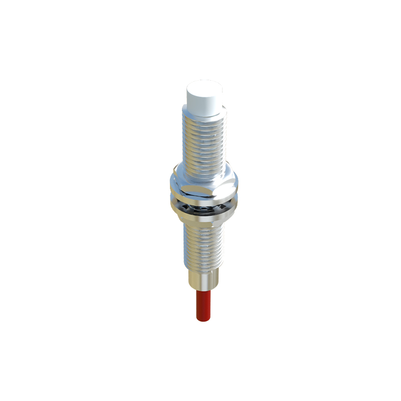
In conclusion, turbine type proximity sensors represent a mature yet vital technology in the industrial sensor ecosystem. Their ability to provide reliable, contactless speed monitoring in environments that would challenge more delicate sensors ensures their continued relevance. Understanding their operating principle, advantages, and ideal applications is key to effectively implementing them in systems requiring robust rotational speed detection and machinery health monitoring.