For two decades, I've watched pristine laser sensor datasheets meet the unforgiving reality of the factory floor, the mine shaft, and the offshore platform. The gap between theory and practice isn't just a margin of error; it's where projects fail. Forget the basics. Let's talk about what happens when the ideal meets the real.
Experience Correction: The Parameters That Lie

The industry obsesses over specs like precision (µm), repeatability, and sampling rate. In a clean lab, they hold. In实战, they crumble. Take the advertised ±0.05% accuracy. That figure assumes a pristine, stable target. Introduce vibration from a 500-ton press or thermal drift in a steel mill where ambient temperature swings 40°C in a shift, and that error can balloon to ±0.5% or more. The real metric isn't static accuracy but *dynamic stability*. I've validated sensors where the baseline reading "walks" over 8 hours of operation due to internal component heating—a phenomenon never mentioned in manuals. Another critical miss: response time. Manufacturers list it in milliseconds. What they don't say is that signal processing algorithms for noise suppression in dirty environments (e.g., airborne oil mist, dust) can add 15-20ms of latent lag, making high-speed闭环 control unstable. You must pressure-test the *entire signal chain* under duress, not the sensor in isolation.
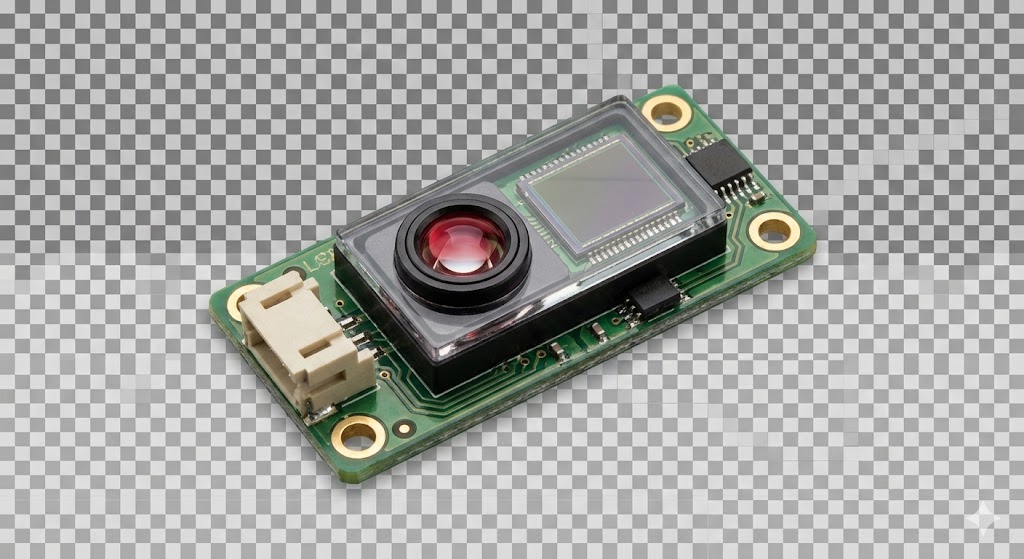
Boundary Conditions: When to Walk Away
This technology is not a universal solution. Deploying it blindly is an invitation for catastrophic failure.
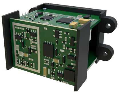
1. Plasma-Rich and High-Arc Environments: Near welding stations or heavy electrical arcing. The intense electromagnetic interference (EMI) can saturate the sensor's photodetector, causing permanent calibration shift or complete lock-up. Shielding often fails. The risk is not just bad data but a sensor that silently provides plausible yet dangerously incorrect readings.
2. Condensing Atmospheres and Hydrophobic Coatings: A major pitfall. Many sensors boast an IP67 rating, which protects against water jets but not against condensation forming on the optics inside a cold housing in a humid environment. Once the lens fogs, the system is blind. Anti-fog coatings are often temporary. In applications like food processing with washdowns or maritime environments, this is a dominant failure mode. If you see rapid thermal cycling with high humidity, reconsider.
3. Targets with Subsurface Scatter or Low Optical Contrast: Measuring the position of clear glass or detecting a black rubber belt on a black conveyor. The laser may penetrate or be entirely absorbed, yielding a return signal with a poor signal-to-noise ratio. Increasing laser power to compensate can be unsafe and often violates Class 1 laser safety regulations for factory automation. This is a fundamental physical limit.
4. Ultra-High-Speed Applications on Non-Cooperative Surfaces: Measuring the vibration of a fan blade or the profile of fast-moving, non-reflective textile fibers. The laser spot needs sufficient "dwell time" to get a valid return. Beyond certain speeds (often lower than theorized), you're not measuring the target; you're measuring noise. Pulsing lasers can help, but their peak power needs careful management to avoid damaging sensitive surfaces.
Counter-Intuitive Conclusion: Sometimes a "Worse" Sensor is the Better Tool
The most reliable system is not always the one with the highest specification. Here’s the data-driven heresy:
* Redundancy with Lower Precision Beats a Single High-Precision Unit: In a critical thickness monitoring application for rolling mills, we deployed two mid-tier laser sensors in a triangulated setup instead of one premium unit. The combined data, filtered through a consensus algorithm, provided a more robust and fault-tolerant measurement. When one sensor was temporarily occluded by steam, the system remained operational. The uptime increased by over 300% compared to the previous "high-precision" solution that failed under the same condition. The cost was similar, but reliability soared.
* Analog Output Can Be More Robust Than Digital Bus Communication: In high-EMI environments, the noise immunity of a 4-20mA analog loop often surpasses that of a digital fieldbus (e.g., IO-Link, EtherCAT). The digital signal, while rich in data, is vulnerable to corruption from variable-frequency drives or welding equipment, leading to communication dropout. The humble analog signal, properly shielded, provides continuous, glitch-free operation. Chasing "smart" connectivity can introduce the single point of failure you sought to avoid.
* Calibration Interval is Inversely Related to Thermal Cycling, Not Operating Hours: The primary driver of calibration drift is not how long the sensor is on, but how many times it undergoes thermal expansion and contraction. A sensor in a climate-controlled lab may hold calibration for years. The same sensor on a machine that cycles on/off daily may require quarterly recalibration. Tracking power cycles and ambient temperature variance is a better predictor of needed maintenance than simple runtime.
The ultimate insight is this: The value of a laser sensor is not defined in its brochure, but in its carefully scoped application within the chaotic, noisy, and demanding real world. Select not for peak performance, but for predictable degradation and known failure modes you can manage.