Have you ever wondered what's inside the small, rugged device that reliably detects metal objects on factory floors or in automated gates? Metal proximity switch sensors are ubiquitous in industrial automation, known for their durability and non-contact operation. This guide provides a detailed, hands-on look at the internal components of a typical inductive metal proximity sensor through a careful teardown process. Understanding its construction not only satisfies technical curiosity but also aids in troubleshooting and appreciating the engineering behind these workhorses.
Before beginning any disassembly, safety is paramount. Ensure the sensor is completely disconnected from any power source. The device we are examining is a standard cylindrical DC inductive proximity switch, commonly rated for 10-30V DC, with a sensing range of a few millimeters to several centimeters, housed in a threaded metal barrel.
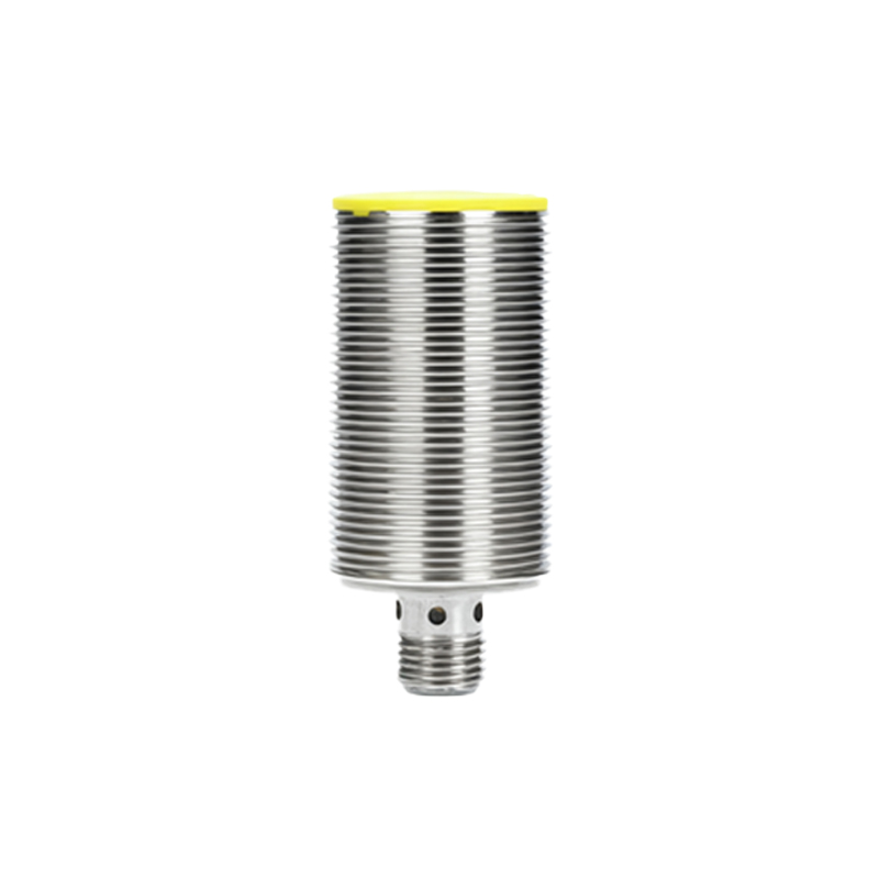
The external casing is the first line of defense. Typically made of nickel-plated brass or stainless steel, the barrel is robust. The sensing face is a polymer cap, often made of PBT or similar plastic, which allows the electromagnetic field to pass through while protecting the internal coil. The rear features a connection area, usually with pre-wired leads or a connector socket, potted with epoxy to create a strain relief and environmental seal. This potting compound is the first significant challenge. It is a hardened, rubbery material designed to be waterproof (often IP67 rated) and vibration-resistant. Carefully scoring around the cable entry with a utility knife can help. For sensors with an integral connector, the back cover may be threaded or crimped.
Using appropriate tools like small screwdrivers, pliers, and a heat gun (applied cautiously), we work to separate the rear housing. Patience is key to avoid damaging components. Once the potting compound is removed or the end cap is unscrewed, the internal assembly slides out from the metal barrel.
The core assembly reveals a logical layout. At the very front, directly behind the sensing face, sits the heart of the sensor: the ferrite core and coil. This is a carefully wound copper coil surrounding a ferrite core, which concentrates the oscillating electromagnetic field generated by the circuit. The coil is soldered to a small printed circuit board (PCB).
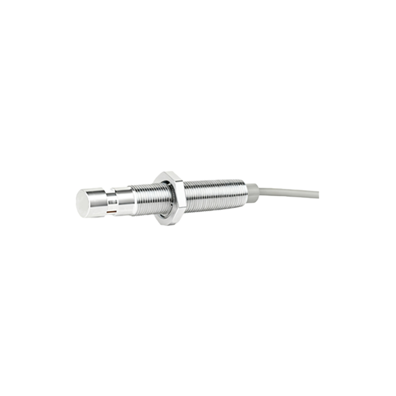
The PCB, usually a single-sided or double-sided board, hosts the oscillator circuit, demodulator, trigger, and output switching components. The oscillator, involving a transistor or a dedicated IC, generates the high-frequency field. When a metal object enters this field, eddy currents are induced in the object, damping the oscillation. This change is detected by the demodulator stage. A Schmitt trigger circuit then provides a clean switching signal to the output stage.
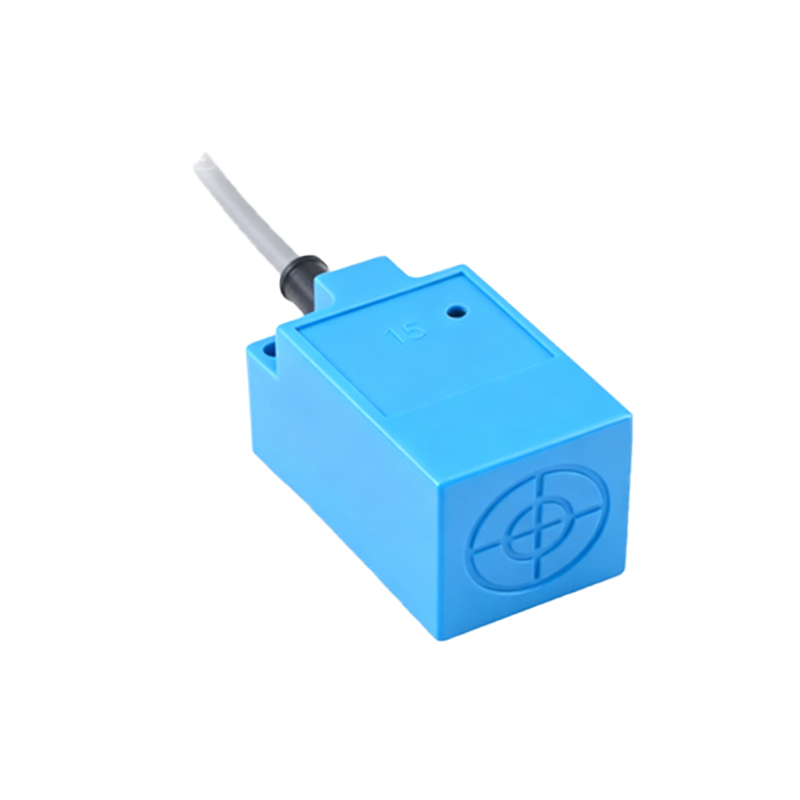
The output stage is prominently featured on the PCB. For a 3-wire DC sensor, you will find a power regulation section (often a simple voltage regulator or zener diode) and the solid-state switch. The most common output is an NPN or PNP transistor. In many sensors, a bright LED indicator is also present, connected in series with a current-limiting resistor.
All components are typically through-hole soldered for mechanical strength. The board is compact, with components placed to fit the cylindrical form factor. Conformal coating—a thin polymer layer—is often visible on the PCB, protecting against moisture and condensation.
After the PCB, we find the spring contacts or wiring that connect the output to the external connector or cable. Finally, the assembly is completed by various O-rings and seals that ensure the integrity of the housing.
Reassembly is the reverse process, though it's important to note that after such a teardown, the environmental sealing (IP rating) is almost certainly compromised. The potting compound cannot be reliably restored without specialized equipment.
This internal simplicity is deceptive. The robustness comes from the quality of components, the precision of the coil winding, the stability of the oscillator circuit, and the thoroughness of the sealing. Failures, when they occur, often stem from cable breakage at the strain relief, water ingress due to seal failure, or, less commonly, component failure on the PCB from voltage spikes.
By disassembling a metal proximity switch, we gain a concrete understanding of its operational principles—from the oscillating electromagnetic field to the solid-state electronic switch. This knowledge underscores why these sensors are so reliable: they have few moving parts, and their design is focused on shielding the core electronics from harsh industrial environments. Next time you see one on a machine, you'll visualize the intricate world of coils, circuits, and potting compound working silently inside that metal shell.