Proximity sensors are indispensable components in modern industrial automation, safety systems, and countless electronic devices. Their ability to detect the presence of nearby objects without physical contact makes them reliable and long-lasting. Among the various types, inductive proximity sensors are specifically designed for detecting metallic objects. This article delves into the fundamental circuit diagram of a basic inductive proximity sensor for metal detection, explaining its core components and operational principles in a clear, non-technical manner.
At the heart of an inductive proximity sensor lies a coil of wire wound around a ferrite core. This assembly forms an inductor, which is the key sensing element. The complete circuit typically integrates this inductor into an oscillator circuit. A common and effective design utilizes a simple LC tank circuit, where the inductor (L) is paired with a capacitor (C). This LC circuit is connected to a transistor amplifier, often in a Colpitts or Hartley oscillator configuration, which generates a high-frequency alternating magnetic field around the coil.
Under normal conditions, when no metal target is within the sensor's detection range, the oscillator runs freely at its designed resonant frequency. The circuit maintains sustained oscillations, and this status is monitored. The critical change occurs when a metallic object enters the oscillating magnetic field. According to the principles of electromagnetic induction, eddy currents are induced on the surface of the metal. These currents create their own opposing magnetic field, which interacts with the sensor's field.
This interaction effectively increases the "load" on the oscillator coil. The energy loss due to the eddy currents causes a change in the oscillator's characteristics. In most practical sensor circuits, this results in a dampening or a complete cessation of the oscillations. The circuit is designed to detect this precise change. Following the oscillator stage is a demodulator and a trigger circuit (often a Schmitt trigger). This stage converts the amplitude change or frequency shift of the oscillator signal into a clean, digital output signal.
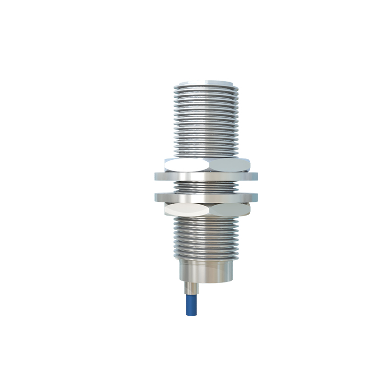
For instance, when oscillations are present (no metal detected), the trigger circuit outputs a HIGH signal (e.g., 5V or 24V, depending on the design). When oscillations are dampened (metal detected), the trigger circuit flips and outputs a LOW signal (0V). This digital signal can then directly interface with programmable logic controllers (PLCs), microcontrollers, or relays to control machinery—stopping a conveyor belt, counting objects, or activating a safety gate.
A practical circuit diagram would include the following key blocks: the LC oscillator with its transistor, a rectifier and filter stage to convert the AC oscillation signal to a DC voltage level, a voltage comparator (Schmitt trigger) to provide hysteresis and prevent output chatter, and finally an output driver stage. The output stage could be an NPN or PNP transistor providing a sinking or sourcing output, respectively, compatible with standard industrial wiring.
Designing such a circuit requires careful consideration of factors like detection range, which is influenced by the coil size, oscillator frequency (typically between 100 kHz and 1 MHz), and the type of metal. Ferrous metals like iron and steel are generally detected at longer ranges than non-ferrous metals like aluminum or copper because they exhibit both eddy current and magnetic permeability effects. Shielding is another important aspect; shielded sensor designs have a focused frontal detection field, while unshielded types can detect from the sides as well.
In summary, the metal detection proximity sensor circuit elegantly transforms a physical principle—electromagnetic induction and eddy current generation—into a robust electrical switch signal. Its reliability stems from having no moving parts and its immunity to environmental factors like dust, oil, or moisture (within specified limits). Understanding this core circuit diagram provides a solid foundation for working with these ubiquitous sensors, enabling better selection, integration, and troubleshooting in automated systems. From packaging lines to automotive assembly robots, the simple yet effective inductive proximity sensor circuit remains a cornerstone of industrial sensing.