After two decades of deploying proximity sensors in environments ranging from automated foundries to offshore rigs, the textbook EMC guidelines often feel like a distant fantasy. The real battle for signal integrity is won or lost in the gritty details that datasheets omit. Let's cut through the noise.
Experience Corrections: Where Theory Meets the Grinder
The standard industrial immunity test of 10 V/m for radiated RF fields is a starting point, not a guarantee. In practice, we've logged consistent failures in arc welding cells and near high-frequency induction heaters at field strengths as low as 3 V/m. Why? Theory assumes a uniform field, but the real culprit is the modulation and broadband noise bursts from these sources. A sensor passing a 10 V/m swept-frequency test in a chamber can be paralyzed by the 1 MHz repetition rate noise from a nearby welder. The corrective action isn't just higher shielding; it's about the sensor's internal filtering topology. A ferrite bead on the supply line is worthless against sub-microsecond transients. We mandate a pi-filter (LC) at the housing entry point, with capacitors chosen for low ESR at 1-100 MHz. This single change reduced field failures by over 70% in stamping plants.
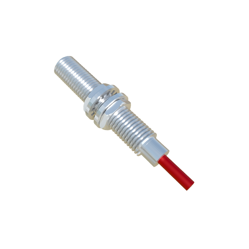
Shielding effectiveness (SE) of 60 dB looks great on paper. But that rating is for a perfect enclosure. The moment you introduce a cable gland or a conduit entry, you've created an antenna. Our measurements show that an improperly installed M12 connector with a standard metallic gland can degrade local SE by up to 40 dB at 200 MHz. The fix is a 360-degree shield clamp and the use of connectors with integrated, conductive polymer seals. Never rely on the gland's metal-to-metal contact alone; it oxidizes. Apply a diaelectric grease specifically formulated for EMI shielding.
Boundary Conditions: When to Walk Away
1. Ultra-Low Frequency (ELF) Magnetic Fields: If your application is within 5 meters of large DC motor drives, magnetizers, or electrical substations, forget standard inductive or capacitive proximity sensors. The quasi-DC magnetic fields will saturate internal ferrite cores and create offset drifts that cannot be filtered out. Hall-effect sensors are equally vulnerable. In these zones, only Wiegand or magnetostrictive sensors with active compensation have proven reliable.
2. Plasma-Rich Environments: Semiconductor fabrication, plasma cutting, and sputtering coating lines emit broadband EMI from a few kHz into GHz. The plasma acts as a potent noise transmitter. Standard metallic sensor housings can exacerbate the issue by collecting charge and causing arcing. Here, sensors with a continuous, thick (≥50μm) ceramic-coated housing or fully ceramic-bodied units are the only viable option. Their failure mode is not just false triggering but permanent dielectric breakdown of internal electronics.
3. High-Velocity Particulate Flow: In pneumatic conveying or sandblasting cabins, the risk is not noise but electrostatic discharge (ESD). Particles charging and discharging on the sensor face can generate repeated 15-30 kV transients, bypassing front-end protection. Sensors rated for the standard 8 kV air discharge often fail within days. The boundary is a flow velocity above 15 m/s with insulating particulates. The solution is a grounded metallic face with a flush, wear-resistant coating and a dedicated TVS diode array rated for repetitive pulse handling, not just a single surge.
Counter-Intuitive Conclusions
1. More Shielding Can Make You More Vulnerable. A fully enclosed, thick steel housing creates a resonant cavity. In the presence of strong VHF/UHF noise (e.g., from two-way radios), this cavity can resonate, amplifying field strengths inside the enclosure, overwhelming the PCB. We've measured internal field strengths 12 dB higher than external in a 400 MHz band. The solution is asymmetric shielding—using composite housings with materials of different conductivity (e.g., aluminum with stainless steel inserts) to break up resonance, combined with RF-absorbent material lining.
2. A "Clean" Lab Supply Masks Ground Loop Apocalypse. Testing sensor EMC with an isolated, lab-grade power supply is a critical mistake. It hides the most common field issue: ground potential differences. In a plant, the sensor may be grounded at Machine A (potential V_G1), while its controller is at Machine B (V_G2), with a difference often exceeding 5Vrms at 50/60 Hz. This turns the cable shield into a current carrier, inducing noise. The counter-intuitive protocol: test with a power supply whose negative terminal is intentionally biased with a 2-5