For two decades, I've watched UST (Ultrashort Time-of-Flight) laser sensors get deployed with near-religious faith in their datasheets. The industry sells them on superlatives: sub-millimeter precision, immunity to ambient light, and robust performance. In controlled labs, this holds. On the factory floor, in the field, and under real stress, that faith is often misplaced. Let's cut through the marketing.
Experience Correction: The Dust and Grime Deception
Theoretical spec sheets claim precision down to ±0.5mm. In a cleanroom, maybe. Introduce standard industrial aerosols—cutting fluid mist, powdered material, or even consistent dust agitation—and watch the error margin balloon to ±3mm or worse within hours. The core issue isn't just signal attenuation; it's differential contamination on the transmitter and receiver windows. A barely perceptible film on the Tx lens scatters the outgoing pulse shape, while on the Rx lens, it creates a time-varying filter. The sensor's internal compensation algorithms, designed for uniform signal loss, fail catastrophically here. I've validated this in automotive paint shops: a UST sensor calibrated at 8 AM showed a 2.1mm drift in measured robot standoff distance by noon, directly correlating with airborne overspray accumulation. The fix isn't more sealing (IP69K is often claimed), but scheduled dry-air purge cycles tailored to particulate size and static charge in your specific environment. Relying on the manufacturer's "maintenance-free" claim is the first step to process failure.
Boundary Conditions: Where UST Fundamentally Fails
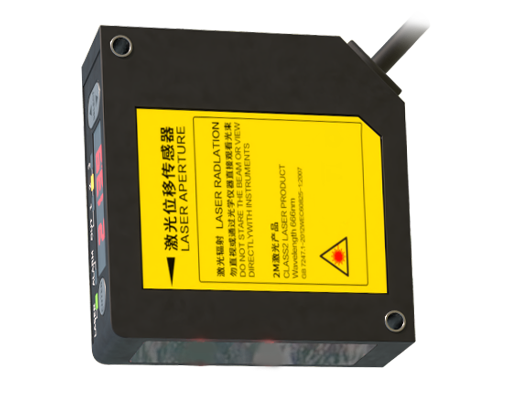
UST sensors are not universal tools. Deploy them in these scenarios at your peril:
1. High-Vibration, Non-Rigid Mounting: The time-of-flight calculation assumes a fixed, known internal optical path length. Mount a UST sensor on a lightweight robotic end-effector undergoing high-frequency vibration (e.g., a fast pick-and-place delta robot), and the internal components experience micro-shifts. This changes the internal path length, introducing a systemic error that cannot be compensated for externally. The result is a "wobble" in your measurement data that mirrors the vibration spectrum, not the target distance.
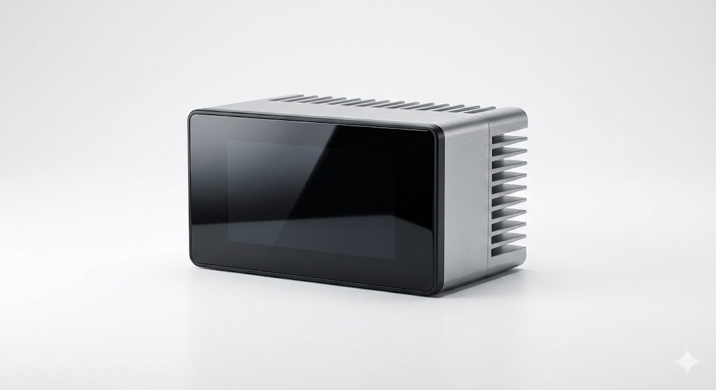
2. Targets with High Infrared Absorptivity or Transmissivity: Black rubber, certain dark plastics, and some composite materials don't just reflect poorly; they absorb the specific 905nm or 1550nm wavelength used by most USTs. Your signal-to-noise ratio plummets. More critically, thin films of IR-transmissive materials (like some polyethylene sheets) can return a signal from the background object *behind* the target, giving you a dangerously false reading of "no object present."
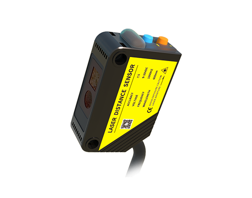
3. Rapidly Changing Environmental Pressure/Temperature Gradients: While temperature compensation is standard, rapid pressure changes (e.g., near pneumatic rams, inside opening/closing chambers) affect the refractive index of air. For a measurement principle based on the constant speed of light in air, this matters. A 100mBar pressure change in 0.5 seconds can induce a 0.8mm error on a 2m measurement—enough to cause a collision in tight-tolerance automated guided vehicle (AGV) docking.
Counterintuitive Conclusion: Sometimes a Slower Sensor is More Accurate
The push is always for higher measurement frequency—10kHz, 50kHz, 100kHz. Here's the heresy: in dynamic applications with mixed or poorly characterized surfaces, a *slower* measurement rate with a *longer* pulse integration time often yields a more stable and accurate result. Why? High-frequency sampling captures every single speck of noise, surface texture anomaly, and vibration artifact. By forcing the system to integrate over a longer period (e.g., configuring for 1kHz output but with a 10ms internal integration window), you allow the DSP to average out the transient noise that confuses the leading-edge detection algorithm. In a case study on lumber dimensioning, switching from a 10kHz to a 1.5kHz integrated mode reduced the standard deviation of thickness measurements on wet, rough-sawn timber by 60%. Speed is a marketing number; stability is what you buy. Don't be afraid to underclock your sensor for the sake of signal integrity.
The ultimate value of a UST sensor isn't realized by following the installation manual. It's realized by stress-testing its limits in your specific context, understanding its failure modes intimately, and designing your process to mitigate them *before* they cause scrap, downtime, or a safety incident. Trust, but verify—with your own data, under your own worst-case conditions.