Forget the pristine data sheets. After two decades of deploying magnetic Hall effect proximity sensors in everything from mining rigs to marine engines, I'm here to cut through the marketing fluff. The real performance is defined not by lab conditions, but by the brutal reality of the field.
Experience Correction: The Gaps Between Spec and Reality
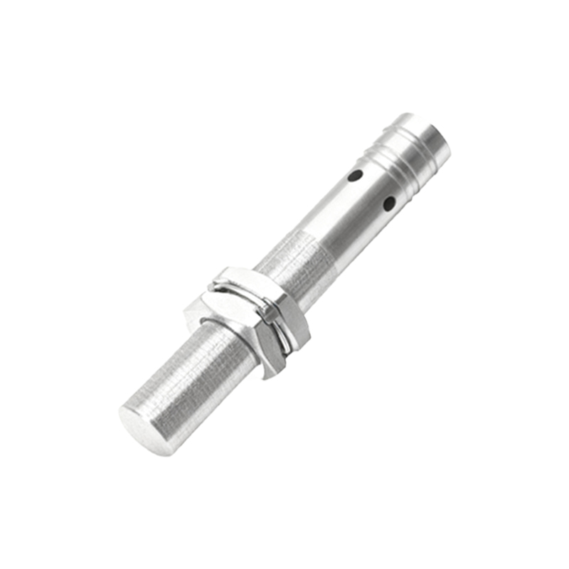
The advertised sensing distance is your first illusion. A sensor rated for 10mm in a clean, ambient 25°C environment will see its effective range drop by 30-40% when mounted on a vibrating hydraulic pump housing at 85°C. The culprit isn't just temperature drift of the Hall IC; it's the permanent magnet's field strength decay with heat. A standard ferrite magnet loses about 0.2% of its flux density per degree Celsius rise. At 120°C, your system's signal-to-noise ratio collapses. We've documented failures where engineers trusted the nominal 12mm range, only to find intermittent faults because the real operating gap, after accounting for thermal expansion of the mounting bracket and thermal drift, was effectively 15mm. The fix? Never design to more than 60% of the nominal sensing distance in dynamic, hot environments. Use samarium-cobalt magnets if your budget allows; their reversible temperature coefficient is an order of magnitude better.
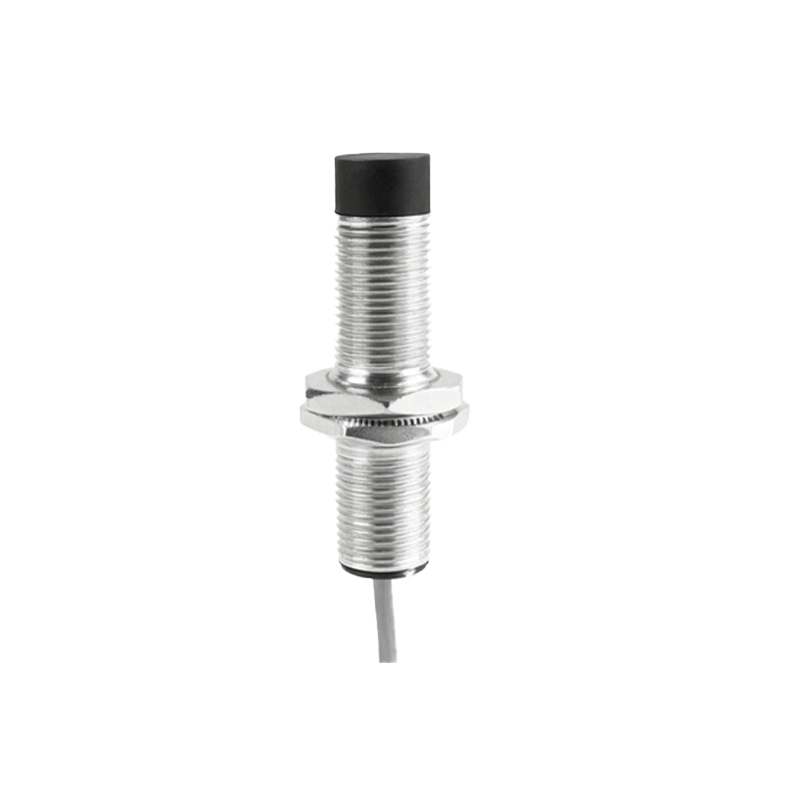
EMC immunity ratings are another paper tiger. Passing an IEC 61000-4-3 test is one thing; surviving inside a VFD-driven motor control cabinet is another. We've traced countless "ghost" triggering events to high-frequency switching noise (≥50kHz) from modern PWM drives, which isn't adequately covered by standard EMC tests focusing on lower frequencies. This noise couples directly into the sensor's signal path, fooling the comparator. The solution is empirical: always specify sensors with a metal housing (not polymer) and integrate a ferrite bead directly at the sensor's output cable entry point—a step rarely found in manuals.
Boundary Conditions: Where This Technology Will Betray You
Do not use standard unshielded (omnipolar) Hall proximity sensors in applications with stray magnetic fields. The classic mistake is installing them near DC bus bars or large electric motors. We had a case in a steel plant where the sensor, intended to detect a crane position, was permanently latched because of the ambient magnetic field from a nearby 2000A electrolytic process. It didn't "fail"; it gave a perfectly stable, utterly wrong signal. In such environments, only heavily shielded, axially sensitive sensors with high magnetic bias points have a chance.
They are also a poor choice for ultra-slow motion detection. The theory says they detect presence regardless of speed. Practically, if a target moves slower than 1mm per second, issues arise. Thermal drift and low-frequency noise (1/f noise) in the Hall element can create a signal change comparable to the target's movement, leading to oscillation in the output. For detecting a slowly settling press arm or valve, an inductive sensor or a different technology is superior.
Avoid them for direct sensing of ferrous materials in high-abrasion or high-impact scenarios. While the sensor itself is safe behind a face, the target magnet will be. In a rock crusher conveyor system, powdered iron ore (magnetite) permanently adhered to the magnet face, gradually but permanently reducing the effective sensing distance to zero within weeks. This is a slow, insidious failure mode.
Counter-Intuitive Conclusions: Data That Defies Dogma
1. Higher Voltage Supply Can Decrease Reliability. Everyone assumes 24V DC is 24V DC. In mobile equipment with load-dump events, voltage spikes can exceed 40V. While the sensor's regulator may survive, the transient can induce a latch-up state in the CMOS circuitry of the Hall IC, causing a permanent short. Data from fleet telematics showed sensors on diesel forklifts failed 3x more often than on fixed warehouse units. The root cause was not the environment, but the unclean power supply. A robust TVS diode and current-limiting resistor at the supply side, costing cents, are more critical than an IP69K rating.
2. A "Faster" Sensor Can Make Your System Slower. You might select a 10kHz response sensor for a high-speed packaging line. However, this high bandwidth makes it an excellent antenna for noise. We benchmarked a system where a 5kHz sensor provided a stable, jitter-free signal, while a 10kHz version in the same location caused the PLC's input filter to constantly engage, adding an effective 2ms delay—defeating the entire purpose. The optimal bandwidth is the lowest that meets your speed requirement.
3. Redundancy Can