Forget the spec sheets. After two decades deploying laser triangulation and time-of-flight sensors in foundries, wastewater plants, and offshore rigs, I've learned that published specifications are often a best-case fantasy. The real performance is dictated by the environment's hostility. Let's cut to the chase.
Experience Correction: Where Theory Meets Grime
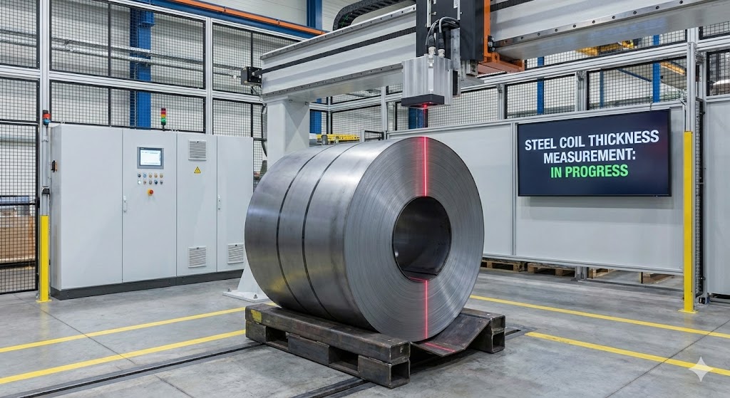
The 0.1% accuracy claim? It assumes a lab-grade, matte white target at 25°C. In reality, surface absorption is your primary adversary. A sensor calibrated for white ceramic will over-report distance by up to 15mm on hot rolled steel due to lower reflectivity. The "maximum range" is a function of surface color and texture, not just laser power. On a dark, porous surface like carbon black, effective range can drop by 40%. Sampling rate is another myth. The advertised 10kHz is achievable only in single-point tracking on an ideal surface. Switch to profile scanning across a weld seam with varying reflectivity, and internal processing algorithms for outlier rejection will throttle your effective data rate by half. Vibration? Factory damping specs are meaningless unless tested at your specific frequency. A 50Hz machine vibration, common in industrial motors, can induce a 0.5mm amplitude error in a sensor rated for 2g vibration, because the damping is optimized for higher frequencies.
Boundary Conditions: When to Walk Away
Laser depth sensors are not universal tools. Deploying them in these scenarios is professional malpractice. First, environments with rapidly changing atmospheric density. The refractive index of air changes with temperature gradients and humidity. In a steel mill's quenching zone, the shimmering hot air layer above a cooling slab can bend the laser beam, causing a "virtual" displacement error of 5-10mm, rendering the data useless. Second, transparent or translucent media. Measuring the fill level of a colorless liquid in a glass tank is a classic failure. The laser will partially reflect off the front and back of the glass, and refract through the liquid, returning a chaotic signal with no coherent peak. Third, highly specular (mirror-like) surfaces. The common belief that a steep incidence angle solves this is dangerous. On a perfect concave specular surface, the laser spot can reflect entirely away from the receiver, giving a catastrophic dropout. Even with diffuse laser sources, a sudden shift in a polished metal sheet's micro-warp can send the return beam outside the receiver's aperture. Fourth, environments with airborne particulates. Dust, mist, or smoke doesn't just attenuate the signal; it creates false return peaks. In a sawmill, wood dust suspended in air can register as a solid surface, tricking the sensor long before the actual beam attenuation limit is reached.
Counterintuitive Conclusions: Data-Driven Heresies
1. Sometimes, a Less Accurate Sensor is More "Accurate." High-precision sensors (e.g., ±10µm) often have smaller optical acceptance angles and laser spots. On a rough, grainy surface like cast concrete, this leads to signal speckle and drastic noise. A more robust sensor with ±100µm accuracy and a larger spot size will average surface irregularities, delivering a more stable and *usefully truthful* measurement of the general plane. Precision is not the same as validity.
2. Calibration is a Compromise, Not a Perfection. You cannot calibrate for all materials. The standard method uses a matte calibration tile. However, creating a multi-material calibration map introduces its own error propagation. The perceived solution becomes a source of instability. It is often more reliable to calibrate for the one primary material and apply a known, fixed offset for secondary materials, accepting a known bias rather than chasing an unstable "correction."
3. The Thermal Worst-Case Isn't Extreme Heat. Everyone worries about high ambient temperature. The most significant thermal drift occurs during warm-up and in cyclic thermal shock. A sensor rated for 0-50°C may achieve its stability spec only after 2 hours of continuous operation. If your process involves opening a furnace door every 15 minutes, the sensor housing experiences rapid cycles, causing lens mount stress and baseline drift that far exceeds the drift listed in the "operating temperature" spec. The data is most unreliable not when it's hot, but when it's getting hot or cold, repeatedly.
4. Processing Power is the True Bottleneck. Modern sensors output massive point clouds. The limiting factor is rarely the sensor's internal processor but the downstream PLC or industrial PC's ability to handle the data stream in real-time. A "slower" sensor with integrated on-board filtering and feature extraction (e.g., outputting just a calculated height and width) can enable a more robust and responsive control loop than a raw data-dumping high-speed sensor that chokes your network and controller.
The takeaway is this: Selecting a laser depth sensor is an exercise in defining failure modes, not in maximizing specifications. Profile the exact failure of your material, environment, and dynamic range. Test with the worst-sample material, not the best. Your goal is not perfect data, but data whose flaws are quantifiable, consistent, and manageable within the control logic. That is the difference between a laboratory curiosity and an industrial tool.